a chamfering machine

A chamfering machine and chamfering technology, applied in the field of chamfering machines, can solve the problems of manpower consumption, low chamfering precision, and low safety factor, and achieve improved stability and standardization, labor cost saving, and high safety factor. Effect

Active Publication Date: 2018-01-23
JOMOO KITCHEN & BATHROOM
View PDF9 Cites 2 Cited by
  • Summary
  • Abstract
  • Description
  • Claims
  • Application Information

AI Technical Summary

Problems solved by technology

However, this chamfering machine has the following shortcomings in the way of manually pushing the workpiece to move: it consumes manpower, has a low safety factor, and the operator is easily cut by the chamfering cutter wheel if the operation is careless; The workpiece is chamfered; it is difficult to maintain a consistent speed of manual movement, resulting in poor chamfering effect and low chamfering accuracy
This kind of chamfering machine also has the following disadvantages in the way that the conveying device is used to push the work to move: there are certain requirements for the load of the conveying device, so that the volume and / or weight of the workpiece cannot be too large, and it is only suitable for lighter and smaller workpieces. For chamfering small workpieces such as wood chips, not suitable for chamfering heavy metal workpieces

Method used


Image

  • a chamfering machine
  • a chamfering machine
  • a chamfering machine

Examples


Embodiment Construction

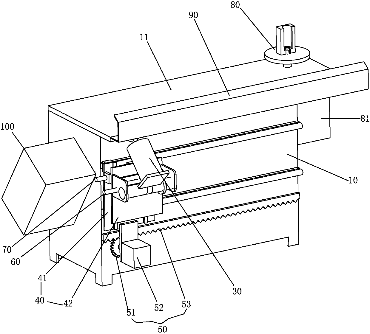
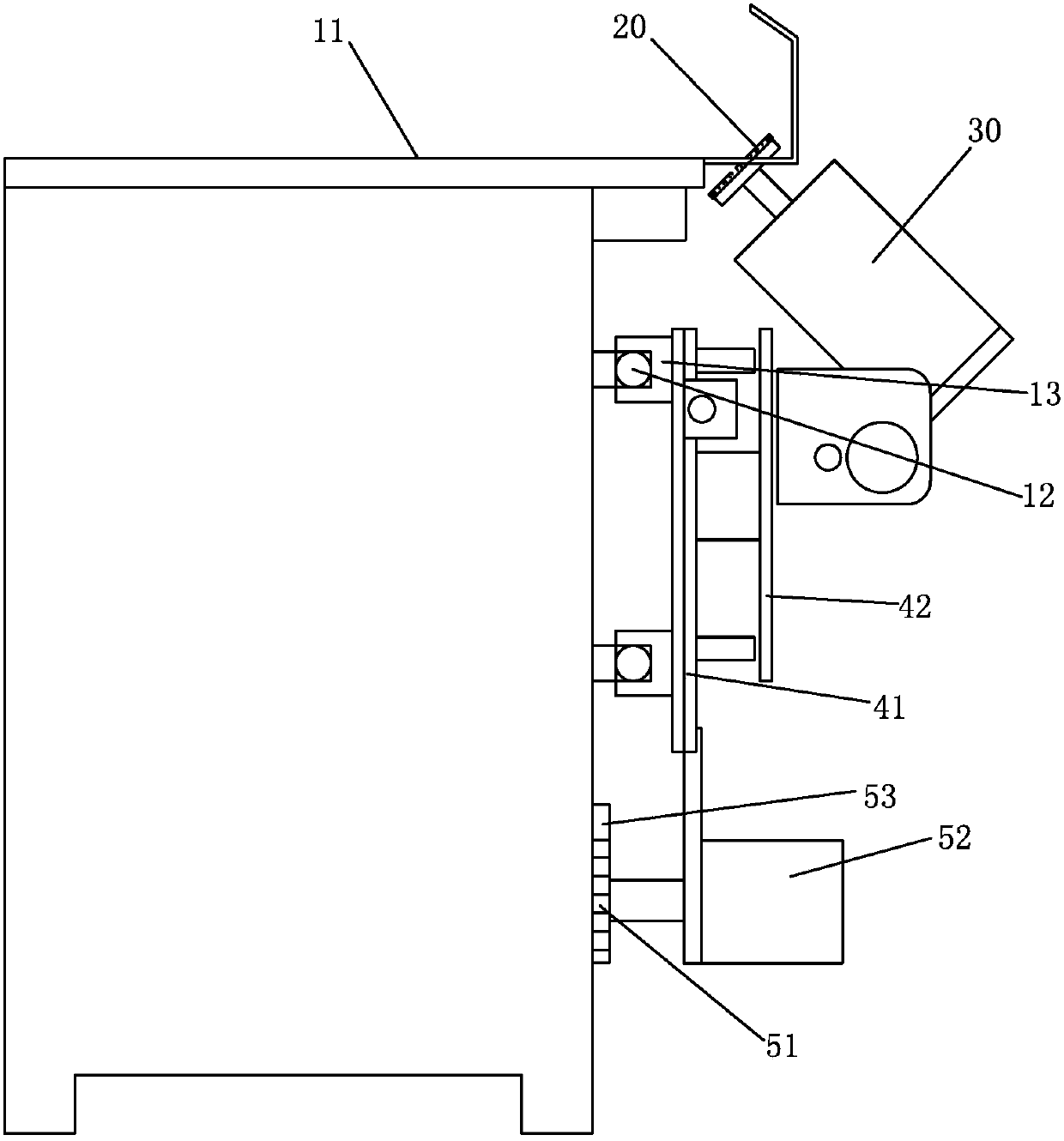
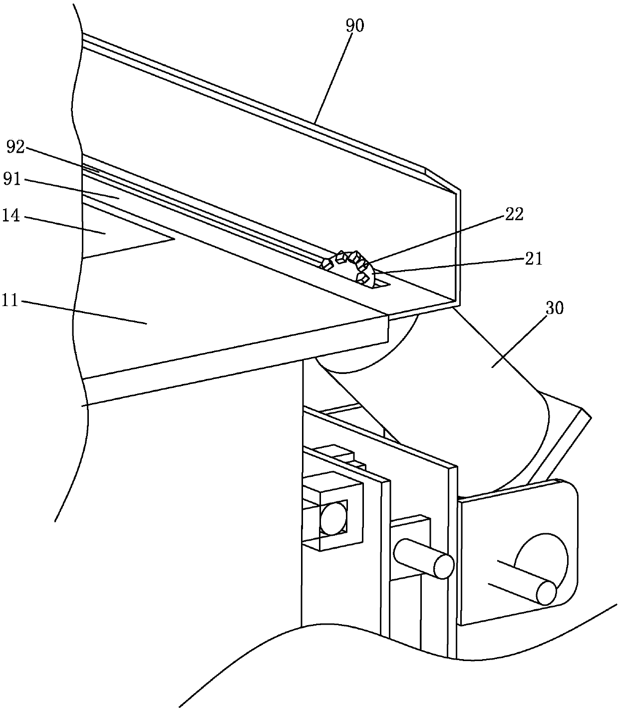
[0032] Examples, see Figure 1-Figure 6 As shown, a chamfering machine of the present invention includes a frame 10, a chamfering tool 20 and a first chamfering motor 30, the frame 10 is provided with a workbench 11, and the chamfering tool 20 is obliquely arranged on the side of the workbench 11 Part, the first chamfering motor 30 is used to drive the chamfering tool 20 to rotate, the first chamfering motor 30 is arranged obliquely, and its motor shaft is inclined upward, and the chamfering tool 20 is installed on the motor shaft of the first chamfering motor 30 . The workbench 11 is provided with a positioning structure for locating the workpiece, and the positioning structure is specifically a magnetic chuck 14 arranged on the workbench 11 . Also comprise movable body 40 and walking drive unit 50, the first chamfering motor 30 is installed on the movable body 40, and this movable body 40 is slidably connected on the frame 10 by sliding guide mechanism, and connects walking ...


PUM


Abstract

The invention discloses a chamfering machine which comprises a rack provided with a working table, a chamfering tool, a first chamfering motor, a movable body and a walking driving device, wherein the chamfering tool is arranged on the side of the working table in an oblique manner; the first chamfering motor drives the chamfering tool to rotate; a positioning structure for positioning a workpiece is arranged on the working table; the first chamfering motor is mounted on the movable body; the movable body is connected onto the rack through a sliding guide mechanism in a sliding manner and is connected with the walking driving device; the walking driving device is used for driving the movable body and the first chamfering motor to walk so as to chamfer the workpiece positioned on the working table. According to the invention, on one hand, the human cost is saved and the security coefficient is high; on the other hand, the walking driving device drives the first chamfering motor to walk so as to enable the chamfering speed to always stay the same, the chamfering precision is high, the chamfering effect is excellent, and the stability and standard during chamfering are improved.

Description

technical field [0001] The invention relates to workpiece processing equipment, in particular to a chamfering machine. Background technique [0002] When processing metal workpieces, it is often necessary to chamfer the workpiece. The traditional method generally uses a grinding machine to chamfer the workpiece, but the grinding machine is manually controlled, which has labor costs, low work efficiency, and low machining accuracy. The size and angle of the chamfer Difficult to control and other deficiencies. At present, there are also many chamfering machines on the market, which generally include a chamfering cutter wheel, a chamfering motor and a worktable. The chamfering cutter wheel is driven by the chamfering motor to rotate. Move on the worktable, use the rotating chamfering cutter wheel to chamfer the workpiece. However, this chamfering machine has the following shortcomings in the way of manually pushing the workpiece to move: it consumes manpower, has a low safety...

Claims


Application Information

Patent Timeline
Patent Type & Authority Patents(China)
IPC IPC(8): B23D79/00B24B9/00B23Q3/15B24B41/06
CPCB23D79/00B23Q3/15B24B9/00B24B41/06
Inventor 林孝发林孝山黄志钱吴承建吴甘贵
Owner JOMOO KITCHEN & BATHROOM
Why Eureka
Try Eureka