
A rotary transport mechanism

A technology of handling mechanism and rotating shaft, which is applied in metal processing, metal processing equipment, manufacturing tools, etc., and can solve problems such as reduced reliability and complex structure

Active Publication Date: 2018-03-20
SUZHOU SECOTE PRECISION ELECTRONICS CO LTD
View PDF7 Cites 0 Cited by
  • Summary
  • Abstract
  • Description
  • Claims
  • Application Information

AI Technical Summary

Problems solved by technology

[0003] In the automatic production process, the transfer and handling of materials is an indispensable link. At present, multiple linear modules such as linear cylinders, rack and pinion mechanisms are generally used for linear transportation, and the combination of multiple linear modules can be realized. Handling in different directions, complex structure and reduced reliability

Method used


Image

  • A rotary transport mechanism
  • A rotary transport mechanism

Examples


Embodiment 1

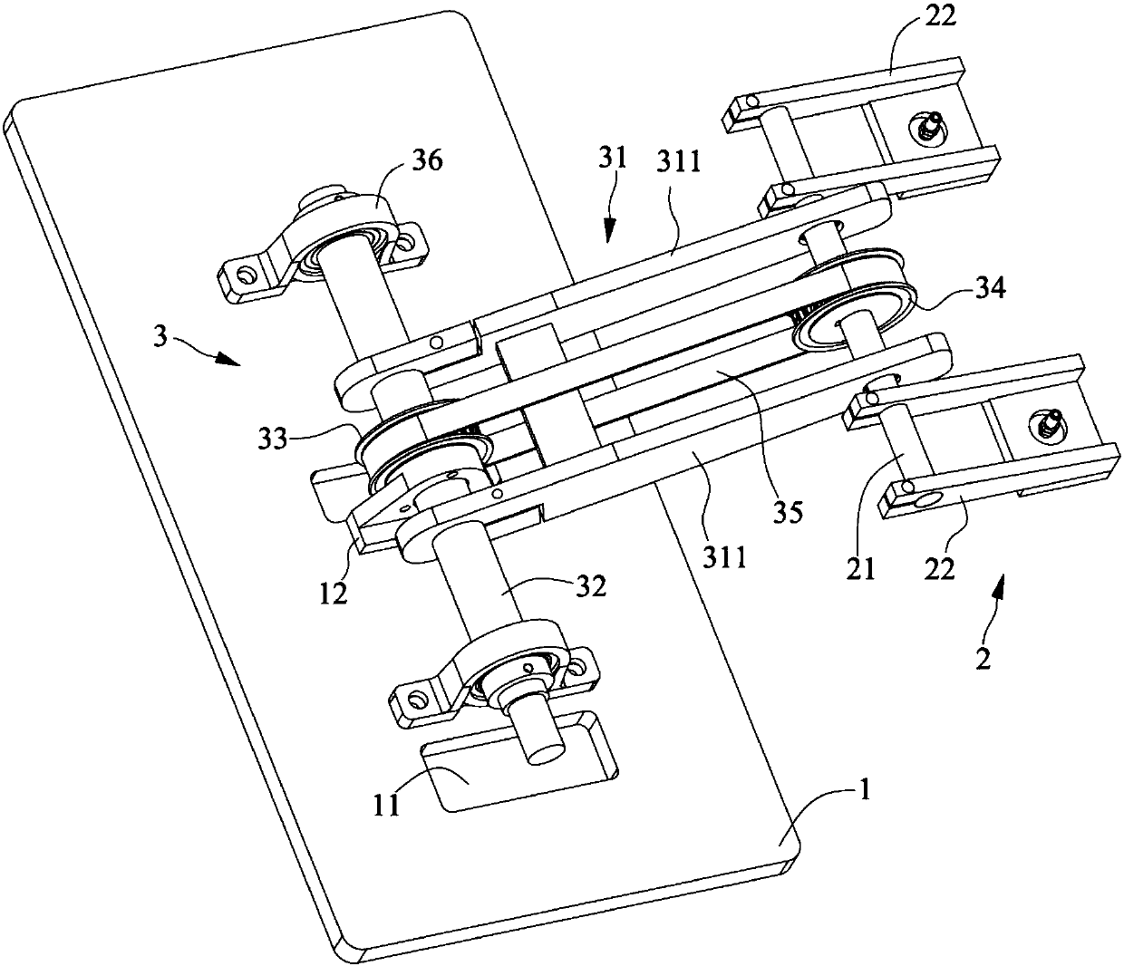
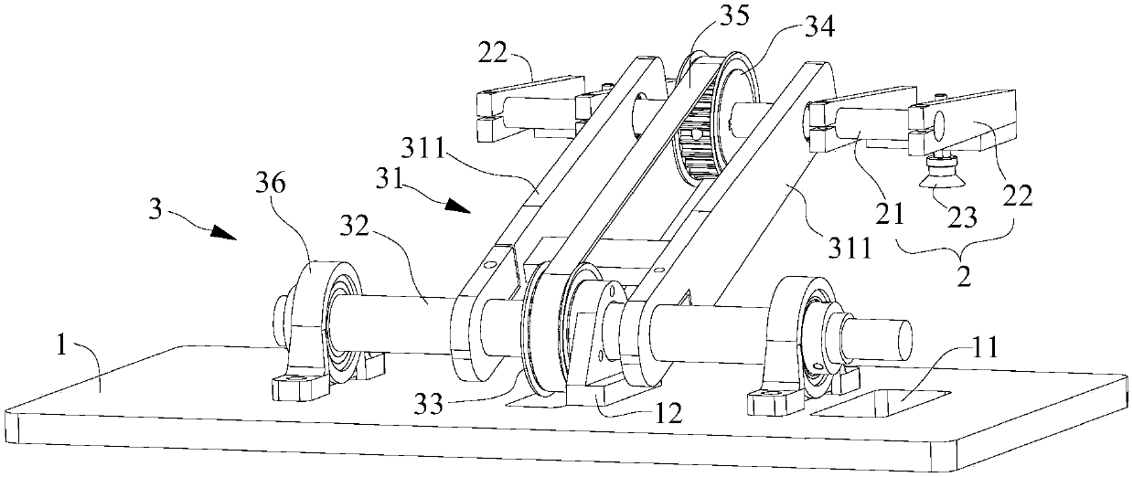
[0023] Please refer to figure 1 and figure 2 , this embodiment provides a rotary transport mechanism, including a base plate 1, a transport assembly 2, a rotary assembly 3 and a rotary shaft driver, and the rotary assembly 3 includes a rotary arm 31, a rotary shaft 32, a first synchronous wheel 33 and a second synchronous Wheel 34, the two ends of rotating shaft 32 are connected to base plate 1, and the bottom end of rotating arm 31 is provided with rotating hole, and rotating shaft 32 passes through rotating hole and first synchronous wheel 33, and first synchronous wheel 33 is relatively fixed with base plate 1, The rotating arm 31 is rotatable with the bottom plate 1, and the transport assembly 2 includes a connecting shaft 21 and a transporting arm 22 for carrying articles. The transporting arm 22 and the second synchronous wheel 34 are fixed on the connecting shaft 21, and the connecting shaft 21 is rotatable. Passing through the top of the rotating arm 31 , the first s...

Embodiment 2

[0027] The difference from Embodiment 1 is that the end of the rotating shaft 32 in this embodiment is fixed on the bottom plate 1, the rotating arm 31 and the rotating shaft 32 can rotate, and the rotating shaft driving part drives the rotating arm 31 to rotate, and no longer drives the rotating shaft. 32 turns. The bottom of the rotating shaft driving part is fixed on the bottom plate 1, and the rotating shaft driving part may include a driving gear, and a sector gear is arranged on the outside of the bottom end of the rotating arm 31, and the sector gear meshes with the driving gear. The rotating shaft driving member can also be a sprocket or a belt pulley, etc., and a corresponding sprocket or belt pulley is arranged outside the bottom end of the rotating arm 31 to directly drive the rotating arm 31 to rotate through a chain or a belt.

Embodiment 3

[0029]The difference from the above-mentioned embodiment is that in this embodiment, one side of the first synchronous wheel is relatively fixed to the bottom plate through a locking device, and the other side is connected to the output shaft of the adjustment motor, and the adjustment motor is fixed to the bottom plate. The locking device includes a friction clutch and The locking seat, the locking seat is fixed to the bottom plate, and the fixing and separation between the first synchronous wheel and the locking seat are realized by adjusting the separation and combination of the clutch plates in the friction clutch. When transporting, by turning the rotating arm, the transporting arm is moved to the attachment of the product to be transported. At this time, the separation of the clutch plate can be adjusted so that the first synchronous wheel and the locking seat are no longer fixed. The rotation of the motor drives the first synchronous wheel to rotate, and then drives the ...


PUM


Abstract

The invention discloses a rotary carrying mechanism. The mechanism comprises a bottom plate, a carrying assembly, a rotating assembly and a rotating driving part, wherein the rotating assembly comprises a rotating arm, a rotating shaft, a first synchronous wheel and a second synchronous wheel; two ends of the rotating shaft are connected to the bottom plate; a rotating hole is formed in the bottom end of the rotating arm; the rotating shaft passes through the rotating hole and the first synchronous wheel; the first synchronous wheel is fixed to the bottom plate; the rotating arm is rotatably arranged at the bottom plate; the carrying assembly comprises a connecting shaft, and carrying arms for carrying articles; the carrying arms and the second synchronous wheel are fixed to the connecting shaft; the connecting shaft rotatably passes through the top end of the rotating arm; the first synchronous wheel and the second synchronous wheel are connected through a synchronizing belt; the rotating driving part is used for driving the rotating arm to rotate. According to the rotary carrying mechanism, the materials are fixed through the carrying arms, then the rotating arm rotates to drive the carrying arms to move through the connecting shaft, so that the materials can be lengthways and transversely carried synchronously; in addition, the state of the carrying arms and the state of the materials are unchanged during the moving process.

Description

technical field [0001] The invention relates to the technical field of conveying machinery, in particular to a rotary conveying mechanism. Background technique [0002] At present, automated production is very common in the manufacturing industry. The use of automated production in mass production can increase labor productivity, stabilize and improve product quality, improve working conditions, reduce production floor space, reduce production costs, shorten production cycles, and ensure production. Balanced, there are significant economic benefits. [0003] In the automatic production process, the transfer and handling of materials is an indispensable link. At present, multiple linear modules such as linear cylinders, rack and pinion mechanisms are generally used for linear transportation, and the combination of multiple linear modules can be realized. Handling in different directions has a complex structure and reduced reliability. Contents of the invention [0004] Th...

Claims


Application Information

Patent Timeline
Patent Type & Authority Patents(China)
IPC IPC(8): B23P19/00
CPCB23P19/001B23P19/007
Inventor 孙丰
Owner SUZHOU SECOTE PRECISION ELECTRONICS CO LTD
Learn More