Electric heating unit and thermal-storage electric boiler with same

An electric heating and electric heating tube technology, which is applied to heat storage heaters, fluid heaters, lighting and heating equipment, etc., can solve problems such as troublesomeness and short average service life, and achieve increased connection structure, convenient operation, and guaranteed use. effect of life

Active Publication Date: 2016-08-31
BEIJING DA ZHENG YONG YE TECH CO LTD
View PDF7 Cites 5 Cited by
  • Summary
  • Abstract
  • Description
  • Claims
  • Application Information

AI Technical Summary

Problems solved by technology

[0004] However, the thermal storage electric boilers on the market usually use electric heating tubes for the internal electric heating unit, and the electric heating unit usually determines the service life of the thermal storage electric boiler, because the electric heating unit is the core component of the thermal storage electric boiler. A large amount of heat needs to be generated, resulting in the shortest average service life of the electric heating unit compared to other components, so a new solution needs to be proposed to prolong the service life of the electric heating unit, thereby prolonging the service life of the thermal storage electric boiler
[0005] Of course, there are also solutions aimed at improving the service life of electric heating units in the prior art, such as the Chinese patent No. "CN2826886Y", which introduces a detachable PTC heater. The first shell and the second shell are relatively fastened and the corresponding two side arms are respectively fixed by fastening screws, and a cavity is formed in the middle part which is suitable for the shape of the PTC heating sheet, and the PTC heating sheet is arranged in the cavity and connected with the conductive sheet The connecting terminals are connected, insulating paper is arranged between the PTC heating sheet and the first shell and the second shell, and heat dissipation fins are respectively provided on the first shell and the second shell. Through this setting, the heating sheet can be easily replaced, but the The scheme still needs to disassemble the first shell and the second shell for replacement and installation during replacement, which is very troublesome

Method used


Image

  • Electric heating unit and thermal-storage electric boiler with same
  • Electric heating unit and thermal-storage electric boiler with same
  • Electric heating unit and thermal-storage electric boiler with same

Examples


Embodiment 1

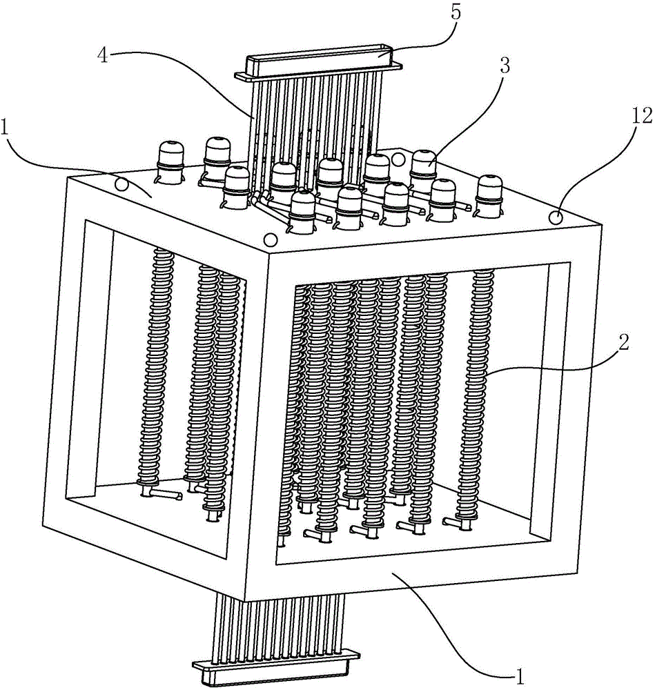
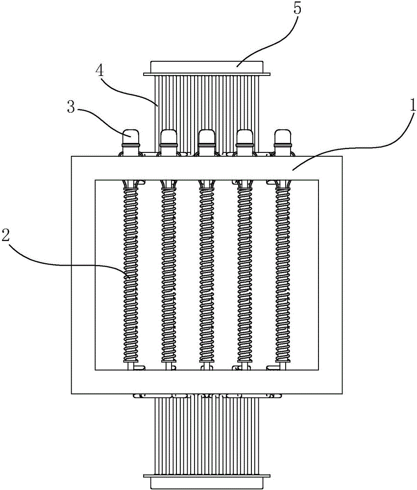
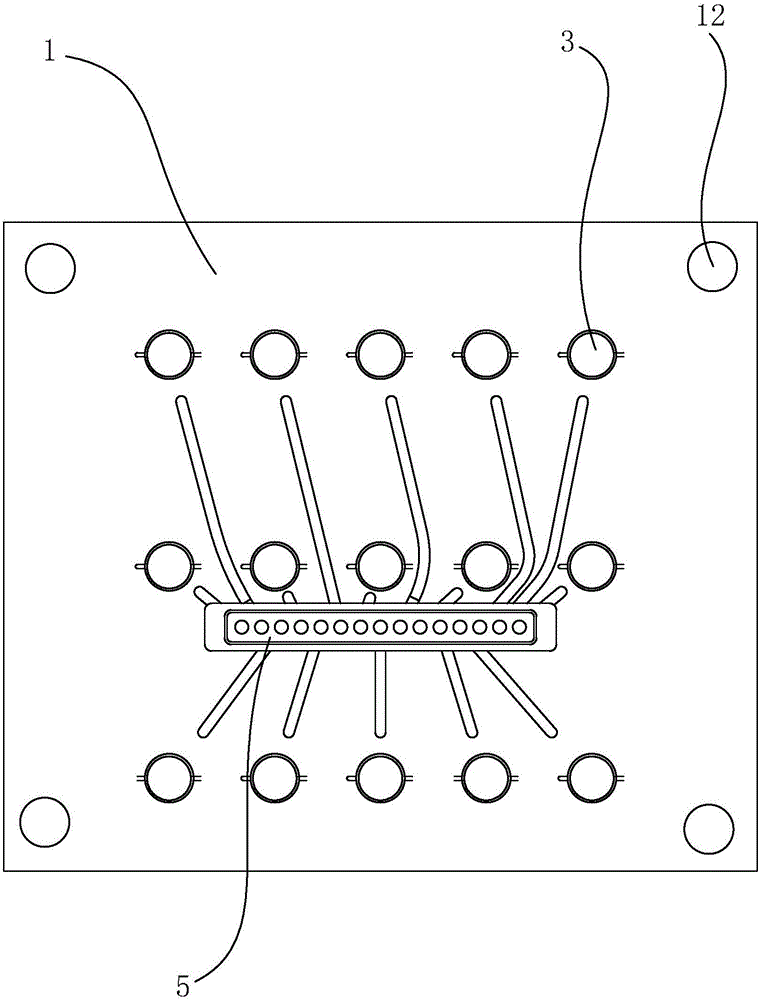
[0044] Embodiment 1: an electric heating unit, such as figure 1 and figure 2 As shown, there are two upper and lower oppositely arranged electric heating tube fixing plates 1 made, and as Figure 4 and Figure 5 As shown, a number of installation holes 7 are opened on the electric heating tube fixing plate 1. The installation holes 7 on the upper and lower two electric heating tube fixing plates 1 are oppositely arranged and their centers are located on the same axis. Between the upper and lower corresponding installation holes 7 The electric heating tube 2 is installed, and the two ends of the electric heating tube 2 are snapped into the installation holes 7 respectively, and a limit assembly is installed in the installation holes 7 for fixing the electric heating tube 2 .

[0045] like Figure 5 As shown, the limit assembly includes a snap ring 8, a hole in the middle of the snap ring 8 is adapted to the electric heating tube 2, and an annular stop protrusion 6 is arrang...

Embodiment 2

[0047] Embodiment two: an electric heating unit, such as Image 6 and Figure 7 As shown, the difference from Example 1 is that the electric heating tube 2 and the snap ring 8 are connected in a different way. An internal thread is provided inside, and an external thread is provided at both ends of the electric heating tube 2, so that the connection mode between the electric heating tube 2 and the snap ring 8 is threaded connection, which can further increase the distance between the electric heating tube 2 and the snap ring 8. The connection is stable, and there will be no accidental detachment due to external vibrations. When installing or disassembling, first press one end of the electric heating tube 2 to the snap ring 8, then make the electric heating tube 2 appear in a vertical state, and then rotate the electric heating tube 2 The heating tube 2 makes the electric heating tube 2 tighten the inside of the snap ring 8 through threads, and then the other end is screwed ag...

Embodiment 3

[0048] Embodiment three: an electric heating unit, such as Figure 8 and Figure 9 As shown, the difference from Embodiment 1 is that the electric heating tube 2 is connected to the snap ring 8 in a different way. In this scheme, a jumping bean spring 10 structure is installed on the inner wall of the hole of the snap ring 8, and the two ends of the electric heating tube 2 are respectively There is a groove 11, so that when the electric heating tube 2 needs to be installed in the snap ring 8, one end of the electric heating tube 2 extends into the hole of the snap ring 8, and then when the electric heating tube 2 is turned, it is in a compressed state. The jumping bean spring 10 just turns into the groove 11 and stretches into the groove 11 to resist it, so that the electric heating tube 2 can be stably fixed, and at this time, under the action of the spring 9, the other end extends into the snap ring 8 In the hole, turn the electric heating tube 2 at this time, the snap ring...


PUM


Abstract

The invention discloses an electric heating unit and a thermal-storage electric boiler with the same. The technical scheme element involves an electric heating unit, which comprises two oppositely disposed electric heating tube fixing plates and a plurality of electric heating tubes mounted between the two electric heating tube fixing plates; a plurality of mounting holes are formed in each of the electric heating tube fixing plates; limit components are mounted in the mounting holes; the limit components are accommodated in the mounting holes, and the mounting holes have cavities allowing the limit components to slip; meanwhile, elastic parts abut and are connected between the limit components and the mounting holes; and the electric heating tubes are removably connected in the limit components. The electric heating unit and the thermal-storage electric boiler with the same provided by the invention are easy to disassemble and maintain, simple in structure and convenient for operation.

Description

technical field [0001] The invention relates to a heat storage electric boiler, more specifically, it relates to a heat storage electric boiler which can be disassembled and installed with an electric heating unit. Background technique [0002] At present, the commonly used heat sources for heating systems or domestic hot water supply systems are coal-fired, oil-fired or gas-fired boilers, but they emit more pollutants and easily pollute the surrounding environment. In recent years, in order to avoid air pollution, there have been The heat storage electric boiler is installed, and the heat storage electric boiler can heat the water in the heat storage tank to 95°C through the circulating pump during the low price and low point of the night, and store it in the heat storage tank in the form of heat energy for use during peak power periods during the day , in order to achieve the purpose of completely avoiding peak hours or reducing electricity consumption during peak hours, a...

Claims


Application Information

Patent Timeline
Patent Type & Authority Applications(China)
IPC IPC(8): F24H7/02F24H9/18
CPCF24H7/0233F24H9/1818
Inventor 刘凯旋
Owner BEIJING DA ZHENG YONG YE TECH CO LTD
Why Eureka
Try Eureka