
Method for geometrically constraining pose based on perspective projection line

A technology of perspective projection and geometric constraints, applied in the field of monocular vision pose calculation, can solve problems such as low measurement accuracy and small measurement range

Inactive Publication Date: 2016-08-31
TIANJIN UNIV
View PDF3 Cites 19 Cited by
  • Summary
  • Abstract
  • Description
  • Claims
  • Application Information

AI Technical Summary

Problems solved by technology

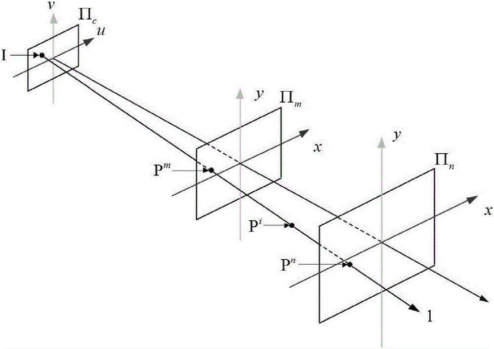
[0003] In order to overcome the deficiencies of the existing technology, solve the non-coplanar P4P problem, solve the problem of the small measurement range and low measurement accuracy of the existing P4P algorithm, and realize the large-scale and high-precision measurement of the target pose, for this reason, the technology adopted in the present invention The scheme is, based on the geometric constraint pose method of perspective projected straight line, set: Π c is the photosensitive plane, 1 is the perspective projection line, point P i is the target point to be measured on the perspective projection line 1, and any perspective projection line 1 passes through the plane Π m and plane Π n , sympathetic light plane Π c At point I, the perspective projection line l is connected with the plane Π m intersection point P m , and plane Π n intersection point P n OK, ignore the depth information of the plane, the plane ∏ ε (x,y) to plane ∏ c In the mapping of (u,v), ε is n or m, and the plane ∏ ε (x,y) and plane ∏ c There is a one-to-one mapping relationship between (u, v). The lower right corner of the aforementioned character combination c, m, n, ε indicates the plane number, the upper right corner m, n, i indicate that the point is located on the plane, g x and g y Represents the rational function corresponding to the plane, u and v represent the image coordinates of the feature points, and define this mapping as:

Method used


Image

  • Method for geometrically constraining pose based on perspective projection line
  • Method for geometrically constraining pose based on perspective projection line
  • Method for geometrically constraining pose based on perspective projection line

Examples


Embodiment Construction

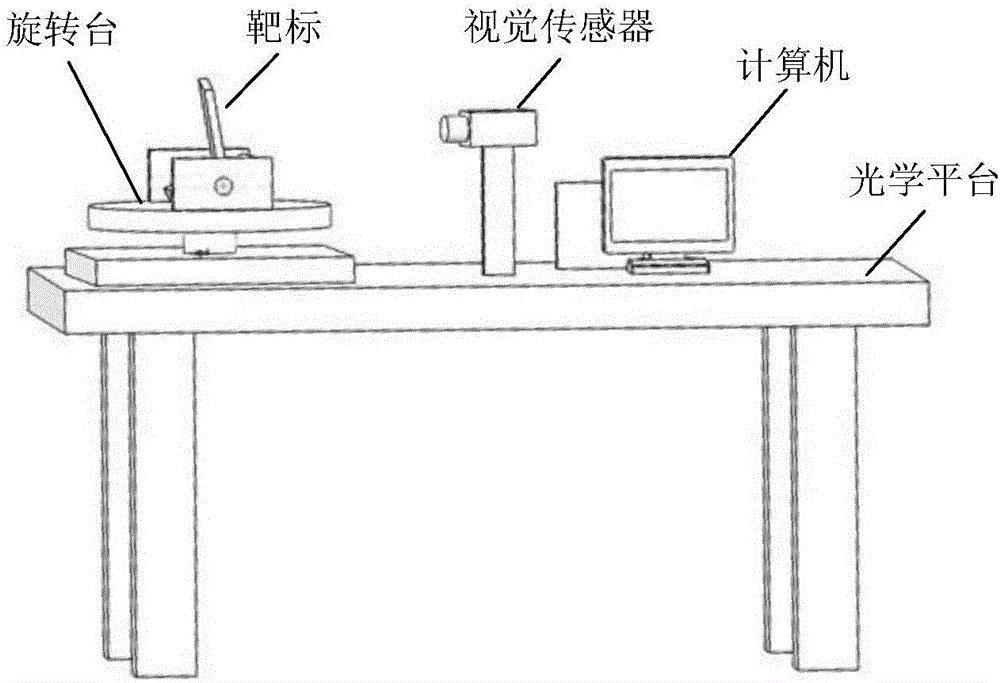
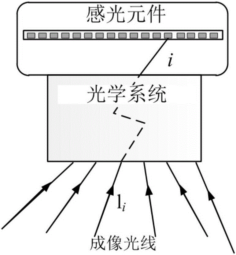
[0036] Such as figure 1 As shown, during the imaging process of the visual sensor, the point on the photosensitive element has one and only one imaging ray corresponding to it. Based on this phenomenon, the present invention proposes a geometrically constrained pose algorithm based on perspective projected straight lines.

[0037] Due to the complexity of the imaging ray path, its mathematical equivalent is a perspective projection straight line in the process of describing the geometric characteristics of the imaging system, such as figure 2 shown. figure 2 in, Π c is the photosensitive plane, 1 is the perspective projection line, point P i is the target point to be measured located on the perspective projection line 1. observe figure 2 It can be seen that any perspective projection line 1 passes through the plane Π m and plane Π n , sympathetic light plane Π c At point I. Then the perspective projection line 1 can be compared with the plane Π m intersection poin...


PUM


Abstract

The invention relates to a monocular vision pose resolving method, which solves the non-coplanar P4P problem, solves the problems that the current P4P algorithm measurement range is small and the measurement accuracy is low, and realizes the large-range high-accuracy measurement of the target pose. The method for geometrically constraining the pose comprises steps of raising a perspective projection line according to a general camera imaging system, establishing and solving an optimal target function of the coordinates of four non-coplanar characteristic points under a camera coordinator system by combining the geometrical constraints between the four non-coplanar characteristic points, solving a rotation matrix and a displacement vector of a target according to the characteristic point coordinator obtained through solution so as to obtain the position and pose parameters of the target. The invention is mainly used for the monocular visual sense pose resolving occasion.

Description

technical field [0001] The invention relates to a monocular vision pose calculation method, in particular to a geometrically constrained pose method based on perspective projection straight lines. Background technique [0002] The monocular vision pose calculation algorithm obtains the target image features through a single visual sensor, and calculates the target's three-dimensional space coordinates from the two-dimensional image features. According to the type of image features, it can be defined as a PnP problem: that is, to obtain the pose information of the target through point feature data. Point feature data generally consists of a series of point pairs, which include object-space identification points and their corresponding projection points. Various solutions to PnP problems, such as EPnP algorithm, DLS algorithm, RPnP algorithm, ASPnP algorithm and LHM algorithm, etc., can solve PnP problems quickly and with high precision. However, the above algorithm is only ...

Claims


Application Information

Patent Timeline
IPC IPC(8): G06T7/00
CPCG06T2207/30244
Inventor 孙长库孙鹏飞王鹏
Owner TIANJIN UNIV
Learn More