Physical convex lens experimental demonstration device

A demonstration device and convex lens technology, which are applied to educational appliances, instruments, teaching models, etc., can solve the problems of high labor intensity, time-consuming and laborious, and the demonstration is not intuitive enough, and achieve the effect of intuitive demonstration and low labor intensity.

Active Publication Date: 2016-08-31
谷蓓蕾
View PDF4 Cites 9 Cited by
  • Summary
  • Abstract
  • Description
  • Claims
  • Application Information

AI Technical Summary

Problems solved by technology

[0007] In order to overcome the shortcomings of traditional manual demonstration, such as insufficiently intuitive demonstration, time-consuming and labor-intensive, and labor-intensive, the technical problem to be solved by the present invention is to provide a physical convex lens experimental demonstration device with intuitive demonstration, time-saving and labor-saving, and low labor intensity

Method used


Image

  • Physical convex lens experimental demonstration device
  • Physical convex lens experimental demonstration device

Examples


Embodiment 1

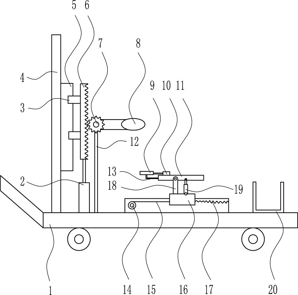
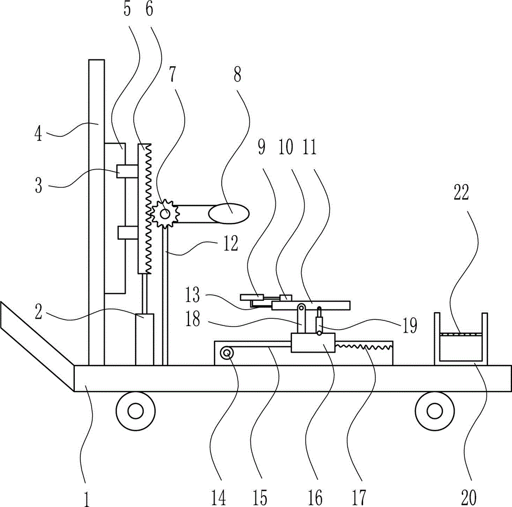
[0020] A physical convex lens experimental demonstration device, such as Figure 1-2 As shown, it includes cart 1, cylinder I2, slider I3, side plate 4, slide rail I5, rack 6, gear 7, convex lens 8, cylinder II 9, push plate 10, placement plate 11, support rod 12, connecting Rod Ⅰ 13, electric winding wheel 14, pull wire 15, slider Ⅱ 16, spring 17, connecting rod Ⅱ 18, cylinder Ⅲ 19, slide rail Ⅱ 20 and processing box 21. The cart 1 is provided with side plates 4 and cylinders from left to right. Ⅰ2, support rod 12, slide rail Ⅱ20 and processing box 21, side plate 4 is provided with slide rail I5, slide rail I5 is provided with slider I3, the upper end of cylinder I2 is connected with rack 6, and slide I3 and rack 6 are connected. Connected, the support rod 12 is rotatably provided with a gear 7, which meshes with the rack 6, a convex lens 8 is connected to the right side of the gear 7, a slider Ⅱ16 is arranged on the slide rail Ⅱ20, and a connecting rod is arranged on the slid...


PUM


Abstract

The invention relates to a demonstration device, and particularly relates to a physical convex lens experimental demonstration device, so as to solve the technical problem of providing a physical convex lens experimental demonstration device with the advantages of intuitive demonstration, time and labor saving and small labor intensity. In order to solve the above technical problem, the invention provides the physical convex lens experimental demonstration device, which comprises a trolley, a first cylinder, a first sliding block, a side plate, a first sliding rail, a rack, a gear, a convex lens, a second cylinder, a push plate, a placement plate, a supporting rod, a first connection rod, an electric winding wheel, a pulling wire, a second sliding block, a spring, a second connection rod, a third cylinder, a third sliding rail and a processing box, wherein the trolley is sequentially provided with the side plate, the first cylinder, the supporting rod, the second sliding rail and the processing box sequentially from left to right; the first sliding rail is arranged on the side plate; the first sliding block is arranged on the first sliding rail; the upper end of the first cylinder is connected with the rack; and the first sliding block is connected with the rack. Effects of intuitive demonstration, time and labor saving and small labor intensity are thus achieved.

Description

technical field [0001] The invention relates to a demonstration device, in particular to a physical convex lens experiment demonstration device. Background technique [0002] Physics is a subject that studies the most general laws of motion of matter and the basic structure of matter. As the leading discipline of natural science, physics studies the most basic forms and laws of motion of all matter, ranging from the universe to elementary particles, and thus becomes the research basis of other natural science disciplines. Its theoretical structure fully uses mathematics as its working language, and experiments are the sole criterion for testing the correctness of the theory. It is the most sophisticated natural science discipline today. [0003] Convex lenses are made according to the principle of refraction of light. Convex lenses are lenses that are thicker in the center and thinner at the edges. Convex lenses are divided into biconvex, plano-convex, concave-convex (or ...

Claims


Application Information

Patent Timeline
IPC IPC(8): G09B23/22
CPCG09B23/22
Inventor 赵忠华
Owner 谷蓓蕾
Why Eureka
Try Eureka