
A submarine cable traction structure and its installation method

A technology of a submarine cable and an installation method, which is applied to the installation of submarine cable traction structure and the field of submarine cable traction structure, can solve the problems of high labor and time, inconvenient operation, and threat to the life safety of operators, and achieves good sealing space and wiring. Convenience and avoidance of the effect of offshore operations

Active Publication Date: 2017-12-19
舟山市华蕴海洋科技有限公司
View PDF9 Cites 0 Cited by
  • Summary
  • Abstract
  • Description
  • Claims
  • Application Information

AI Technical Summary

Problems solved by technology

[0004] The purpose of the present invention is to provide a submarine cable traction structure to solve the problems in the prior art that the stripping of the submarine cable armor requires a lot of manpower and time, the work efficiency is low, the operation at sea is inconvenient and the life safety of the operators is threatened
[0005] Another object of the present invention is to provide a submarine cable traction structure and its installation method, so as to solve the problem that in the prior art, the stripping of submarine cable armor requires a lot of manpower and time, the work efficiency is low, and the operation at sea is inconvenient and threatens the life safety of operators. The problem

Method used


Image

  • A submarine cable traction structure and its installation method
  • A submarine cable traction structure and its installation method
  • A submarine cable traction structure and its installation method

Examples


Embodiment 1

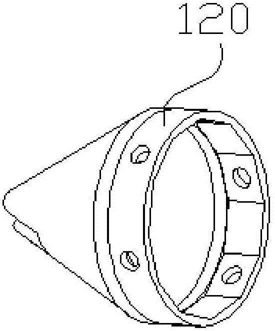
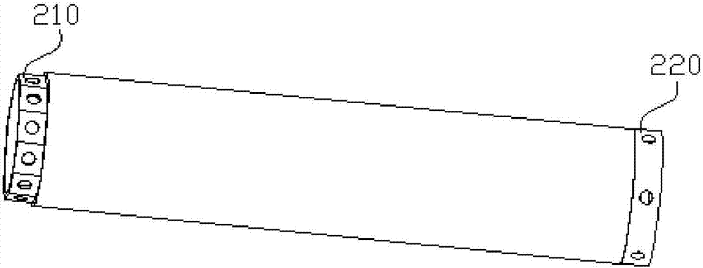
[0050] Please refer to figure 1 , the present embodiment provides a submarine cable traction structure, including a traction joint 100, a sealing tube 200, a sealing head 300 and a traction mesh sleeve 400; the sealing tube 200 is a hollow tubular structure; the traction joint 100 is sealed and connected to one end of the sealing tube 200, The sealing head 300 is connected to the other end of the sealing pipe 200; the sealing head 300 is a hollow structure, and the inner surface of the sealing head 300 is connected with a sealing connection sleeve 310 with a cable matching hole 311; the traction mesh sleeve 400 is arranged in the sealing pipe 200, And the front end of the traction net 400 is connected with the traction joint 100 .

[0051] The submarine cable traction structure in this embodiment is used to connect the submarine cable 500. After the traction structure is connected to the cable, the exposed end of the cable is located in the traction net sleeve, and the tractio...

Embodiment 2

[0071] This embodiment provides a method for installing the traction structure of the submarine cable 500 as in Embodiment 1, and its flow chart is as follows Figure 9 , the installation method includes the following steps:

[0072] Cable armor stripping step: strip the armor at one end of the cable 500 to be installed to expose the core wire 510;

[0073] Optionally, after the cable 500 is sheathed and stripped, a cable joint connection step can be carried out: separate the core wires 510 after stripping the armor, and connect the cable joints 520 to the ends of the core wires 510 respectively, and the cable joints are connected The step is located between the step of stripping the cable armor and the step of installing the sealing head;

[0074] Steps for connecting the traction net sleeve: insert the cable 500 that has been stripped of armor into the traction net sleeve 400 from the rear end of the traction net sleeve 400, so that the core wire 510 is wrapped by the tract...


PUM


Abstract

The invention aims at solving the problems in the prior art that armored cable stripping requires a lot of manpower and time, marine operations are inconvenient and that the life safety of operation personnel is threatened. The invention provides a submarine cable traction structure, comprising a traction connector, a sealing tube, a sealing head and a traction net cover, wherein the traction connector is hermetically connected to one end of the sealing tube, and the sealing head is connected to the other end of the sealing tube; a seal connection sleeve with a cable matching hoe is connected to an inner side face of the sealing head; and the traction net cover is arranged in the sealing tube, and the front end of the traction net cover is connected with the traction connector. The invention further provides a mounting method of the submarine cable traction structure, used for connecting the submarine cable traction structure with a cable. The submarine cable traction structure provided by the invention has the beneficial effects of providing a good sealing space for the cable, and can tract the cable after stripping off the armor of the cable at first, thereby effectively saving the marine operation time, reducing the manpower workload and cost and making the wiring of submarine cables of an offshore wind turbine be more convenient, quicker and safer.

Description

technical field [0001] The invention relates to the technical field of cable laying, in particular to a submarine cable pulling structure. The invention also relates to a method for installing a submarine cable traction structure. Background technique [0002] As the lifeline of input and output of offshore wind farms, submarine cables are the basic guarantee for the normal operation of offshore wind farms. The installation of submarine cables needs to be pulled to the offshore wind turbine platform first, and then installed. [0003] In the prior art, when laying submarine cables for offshore wind turbines, the laying length of the submarine cables is estimated before laying. After cutting, the submarine cables are pulled to the platform of offshore wind turbines through the submarine cable traction net, and then fixed. Strip the armor of the submarine cable on the platform to expose the core wire, then connect the plug and connect it to the corresponding electrical equip...

Claims


Application Information

Patent Timeline
Patent Type & Authority Patents(China)
IPC IPC(8): H02G1/08H02G1/10
CPCH02G1/081H02G1/10
Inventor 朱荣华张美阳宋武梁昊孙香李凤
Owner 舟山市华蕴海洋科技有限公司
Learn More