A continuous double-roll die punching device for circuit boards

A circuit board and roller type technology is applied in the field of continuous-to-roll die punching and forming devices for ultra-long circuit boards. Achieve the effect of continuous work

Active Publication Date: 2018-12-04
QIMAO ELECTRONICS DINGNAN CO LTD
View PDF3 Cites 0 Cited by
  • Summary
  • Abstract
  • Description
  • Claims
  • Application Information

AI Technical Summary

Problems solved by technology

[0003] In the production process, simple PCB boards, such as single-color, double-color, and even three-color LED PCBs, are just simple positive and negative electrodes, which can be directly stamped and formed without graphic transfer, but when encountering an ultra-long PCB board, Generally refers to the length of 1.2M and above, which will bring great difficulties to stamping. First, the mold is very long, fragile and has a short life. In addition, the work efficiency is not high.

Method used


Image

  • A continuous double-roll die punching device for circuit boards
  • A continuous double-roll die punching device for circuit boards
  • A continuous double-roll die punching device for circuit boards

Examples


Embodiment 1

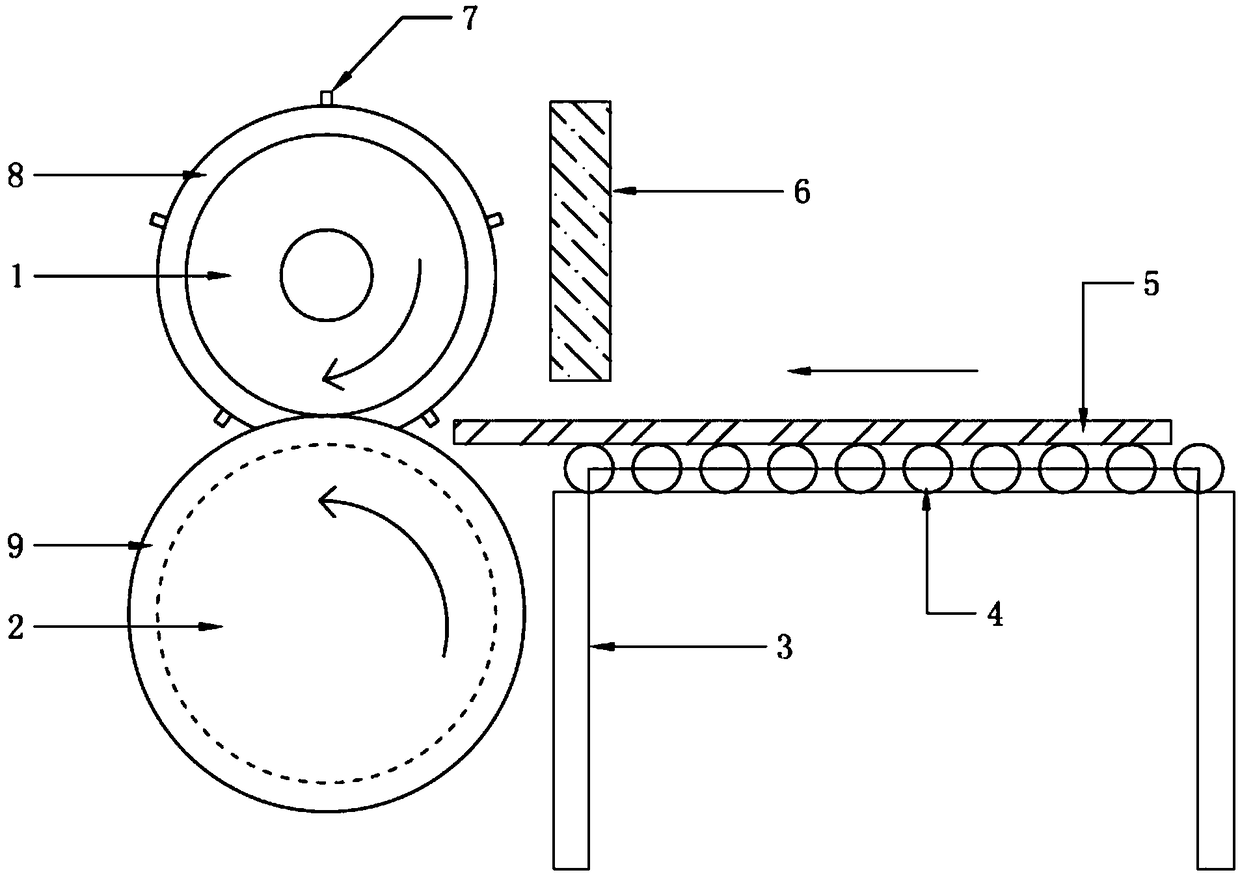
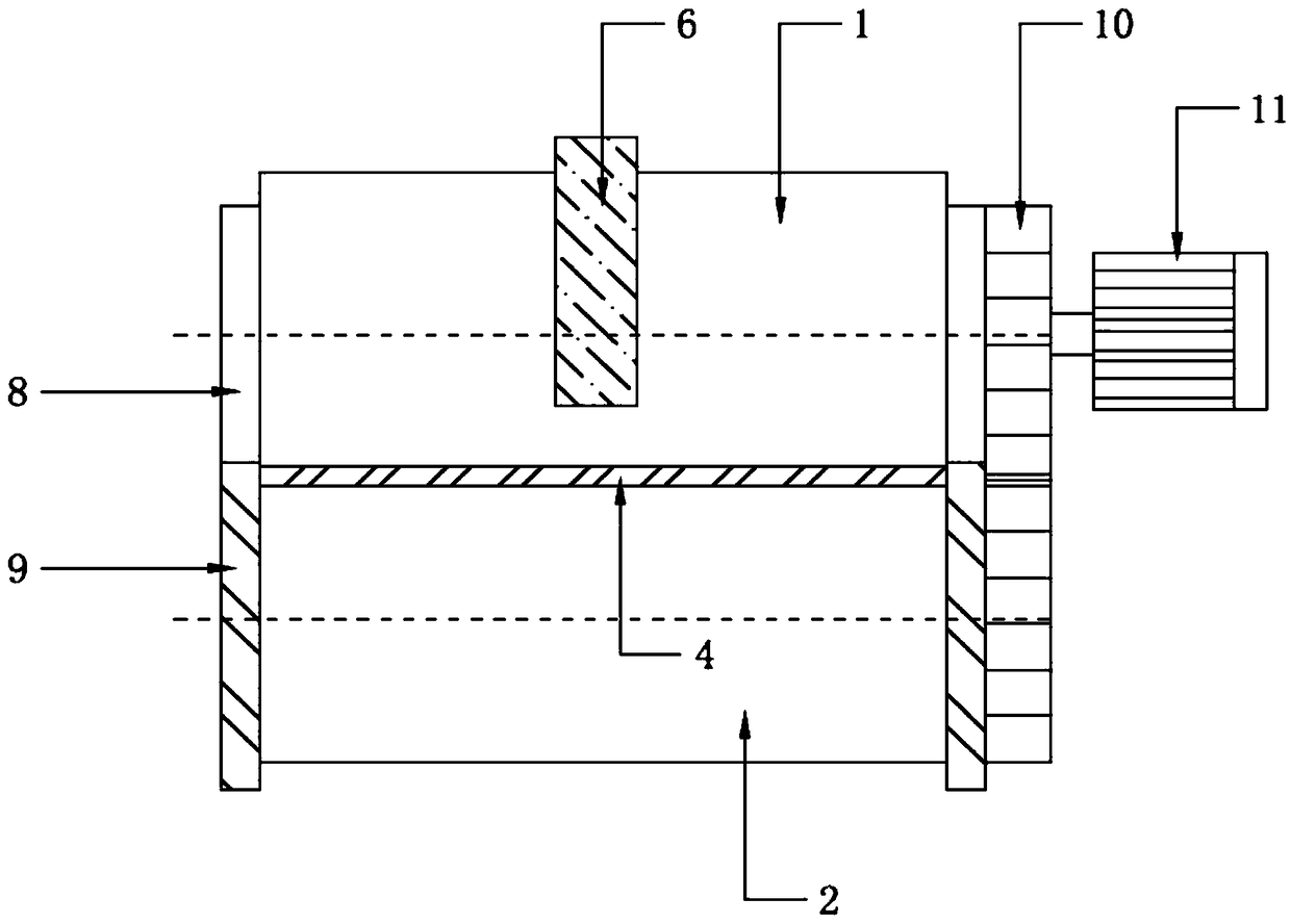
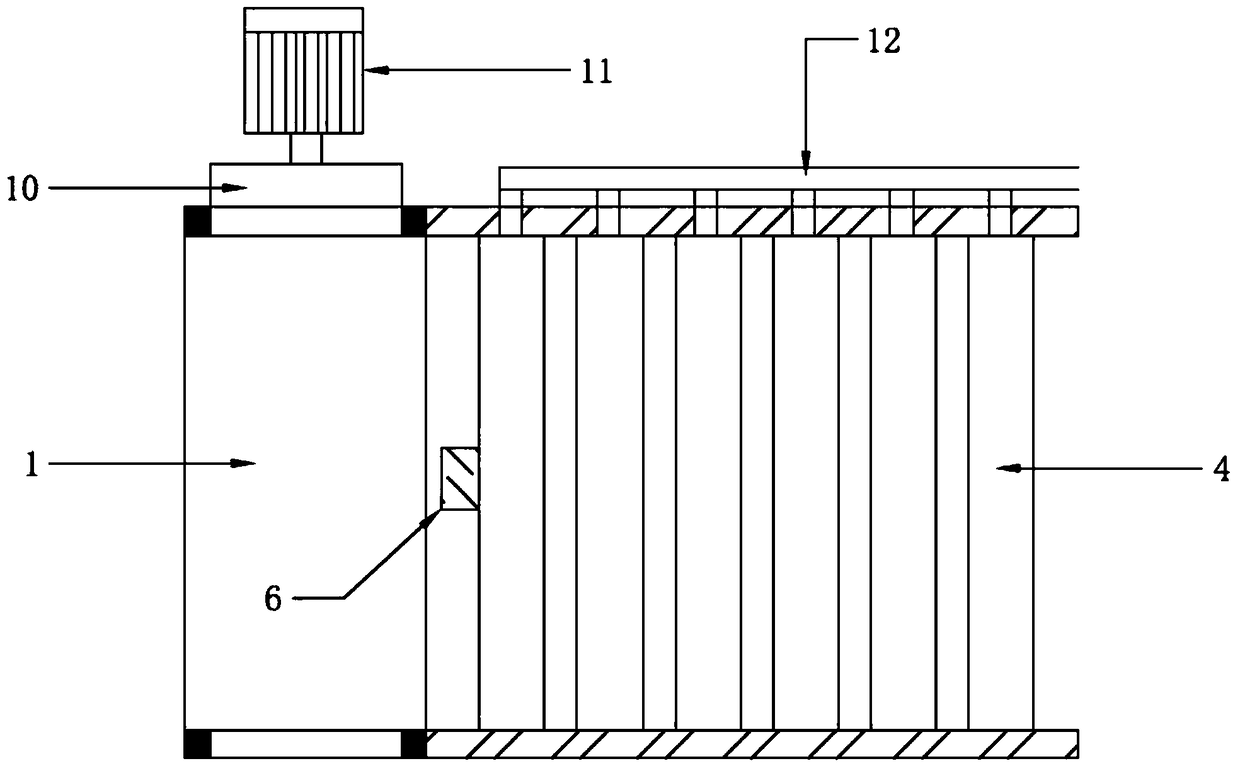
[0019] A continuous pair-roller die punching and forming device for a circuit board includes an upper roller body 1 and a lower roller body 2. A mold (not shown), the upper roller body 1 and the lower roller body 2 are provided with a row of feeding rollers 4 on the side of the plane where the upper roller body 1 and the lower roller body 2 are engaged. The feeding rollers 4 are arranged on the feeding work frame 3 and pass through a conveyor belt. 12 Uniformly connected to a conveying motor (not shown), the feeding work frame 3 is provided with a sensor 6 above one end near the upper roller body 1, and the sensor 6 is connected to a PLC (not shown), and the PLC is connected to control a pair of The roller motor 11 and the counter-roller motor 11 are connected to the upper roller body 1, and the upper roller body 1 and the lower roller body 2 are interlocked and connected with each other through a transmission gear 10.

[0020] The lower roller body 2 has an internal hollow struc...

Embodiment 2

[0022] A circuit board continuous pair-roll type punching and forming device, comprising an upper roller body 1 and a lower roller body 2. The upper roller body 1 is provided with a convex mold 7, and the lower roller body 2 is provided with a concave corresponding to the convex mold 7. A mold (not shown), the upper roller body 1 and the lower roller body 2 are provided with a row of feeding rollers 4 on the side of the plane where the upper roller body 1 and the lower roller body 2 are engaged. The feeding rollers 4 are arranged on the feeding work frame 3 and pass through a conveyor belt. 12 Uniformly connected to a conveying motor (not shown), the feeding work frame 3 is provided with a sensor 6 above one end near the upper roller body 1, and the sensor 6 is connected to a PLC (not shown), and the PLC is connected to control a pair of The roller motor 11 and the counter-roller motor 11 are connected to the upper roller body 1, and the upper roller body 1 and the lower roller ...

Embodiment 3

[0025] The difference between this embodiment and the first embodiment is that a single-chip microcomputer is used instead of a PLC to receive signals from the sensor 6 and issue simple commands to control the roller motor 11.


PUM


Abstract

The invention relates to the technical field of PCB stamping, and provides a continuous pair-roller-type die stamping forming device of an ultra-long circuit board. The continuous pair-roller-type die stamping forming device is characterized in that the device comprises an upper roller body and a lower roller body, convex dies are arranged on the upper roller body, concave dies corresponding to the convex dies are arranged on the lower roller body, a row of feeding rollers are arranged at one side of an engaged plane of the upper roller body and the lower roller body. The feeding rollers are arranged on a feeding working frame and are uniformly connected with a feeding conveying motor through a conveying belt. A sensor is arranged above one end, close to the upper roller body, of the feeding working frame. The sensor is connected with a PLC. The PLC is connected with and controls a pair roller motor. The pair roller motor is connected with the upper roller body. The upper roller body and the lower roller body are engaged with each other through a transmission gear. According to the invention, the pair-roller-type stamping structure is adopted, the ultra-long circuit board is directly punched, the cost and time for pattern transferring are saved; in addition, the infrared diffuse reflection sensor and the PLC are adopted for controlling and completing the die stamping forming of the circuit board, continuous work is realized, and the effect is greatly improved.

Description

Technical field [0001] The invention relates to the technical field of PCB stamping, in particular to a continuous pair-roller die punching forming device for an ultra-long circuit board. Background technique [0002] PCB (Printed Circuit Board), the Chinese name is printed circuit board, also known as printed circuit board, is an important electronic component, a support for electronic components, and a carrier for electrical connection of electronic components. Because it is made by electronic printing, it is called a "printed" circuit board. [0003] In the production process, simple PCB boards, such as monochromatic, bi-color, or even tri-color LEDs, are just simple positive and negative electrodes, which can be directly stamped and formed without graphics transfer. However, when encountering long PCB boards, Generally refers to the length of 1.2M and above, which will bring great difficulties to stamping. First of all, the mold is very long, vulnerable and short in life, and ...

Claims


Application Information

Patent Timeline
Patent Type & Authority Patents(China)
IPC IPC(8): H05K3/00
CPCH05K3/0014H05K2203/0143
Inventor 黄喜军郭张伟
Owner QIMAO ELECTRONICS DINGNAN CO LTD
Why Eureka
Try Eureka