Supercharge Your Innovation With Domain-Expert AI Agents!

A maintenance work light

A work light and work technology, which is applied to lighting auxiliary devices, lighting and heating equipment, electric lighting devices with built-in batteries, etc., can solve the problems of difficult maintenance work, troublesome maintenance work, easy loss, etc., and achieve a simple and reliable structure. , The effect of convenient manufacture and loss prevention

Active Publication Date: 2019-03-19
余姚新大利电器塑料有限公司
View PDF4 Cites 0 Cited by
  • Summary
  • Abstract
  • Description
  • Claims
  • Application Information

AI Technical Summary

Problems solved by technology

Although such maintenance lights solve the problem of inconvenience, when maintenance personnel need concentrated light for observation, they cannot complete the task
Moreover, during maintenance, it is often necessary to adjust the part illuminated by the light, but the existing maintenance lights cannot automatically realize this function, and maintenance personnel need to manually adjust
When maintenance personnel are performing maintenance, it is difficult to free up one hand to adjust. In this case, the existing maintenance lights will make the maintenance work very difficult and time-consuming.
[0003] In addition, the maintenance personnel often remove the screws or nuts during maintenance. At present, these parts cannot be stored well and are easy to be lost, especially in these spaces with insufficient light, which also brings troubles to the maintenance work. big trouble

Method used


Image

  • A maintenance work light
  • A maintenance work light

Examples


Embodiment Construction

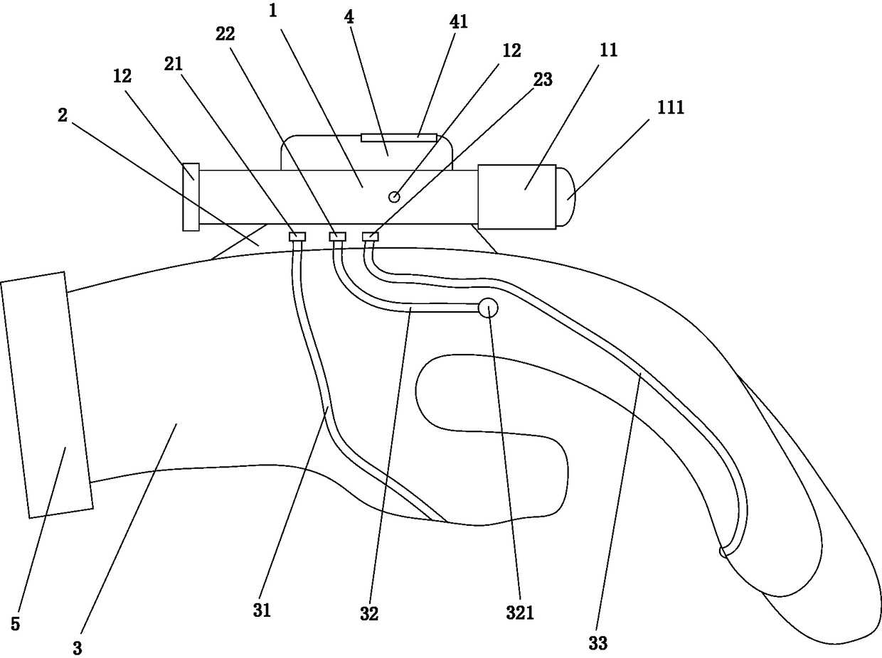
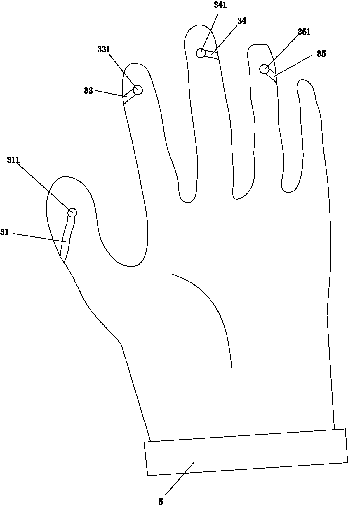
[0016] Below in conjunction with accompanying drawing and specific embodiment the present invention will be described in further detail: Figure 1 to Figure 2 As shown, a work lamp for inspection and maintenance includes a lamp body 1 and a motor base 2 on which the lamp body 1 is installed. It is connected with the lamp body 1 and can control the rotation of the lamp body 1. The motor base 2 is provided with a first joint 21, a second joint 22 and a third joint 23 on the side of the thumb. A fourth joint and a fifth joint are arranged on the side of the little finger, and the thumb, index finger, middle finger and ring finger of the work glove 3 are respectively provided with a first contact 311, a third contact 331, a fourth Contact 341 and fifth contact 351, the middle part of the side of the index finger of the work glove 3 is provided with a second contact 321, the first contact 311, the second contact 321, the third contact The point 331, the fourth contact 341 and the ...


PUM


Abstract

The invention discloses an overhaul working lamp. The overhaul working lamp comprises a lamp body and a motor base provided with the lamp body. The motor base is installed on a working glove. A motor is arranged in the motor base. The motor is connected with the lamp body and can control rotation of the lamp body. A first connector, a second connector and a third connector are arranged on the portions, located on one side of a thumb, on the motor base. A fourth connector and a fifth connector are arranged on the portions, located on one side of a little finger, on the motor base. A first contact is correspondingly arranged on the thumb part of the working glove. A third contact is correspondingly arranged on the index finger part of the working glove. A fourth contact is correspondingly arranged on the middle finger part of the working glove. A fifth contact is correspondingly arranged on the ring finger part of the working glove. A second contact is arranged on the middle portion of the lateral side of the index finger part of the working glove. The first contact is correspondingly connected with the first connector. The second contact is correspondingly connected with the second connector. The third contact is correspondingly connected with the third connector. The fourth contact is correspondingly connected with the fourth connector. The fifth contact is correspondingly connected with the fifth connector. Compared with the prior art, by means of the overhaul working lamp, light rays of a large range can be provided for illumination, and the overhaul working lamp can also light up local parts in a concentrated manner.

Description

technical field [0001] The invention relates to a lamp, in particular to an inspection work lamp used for inspection of automobiles, large machine tools or elevators. Background technique [0002] When machines such as automobiles, large machine tools, or elevators break down, maintenance personnel often have to drill into the bottom of the car or the machine tool or go to places such as the elevator room for diagnosis and maintenance. The advent of inspection lights has effectively solved the problem of insufficient light in these spaces. However, due to the narrow space under the vehicle, it is very inconvenient for maintenance personnel to move around, and the inspection light cannot be used on the handle. In the prior art, magnets are generally arranged on the maintenance lamps to be adsorbed on iron parts for operation. Although such an inspection light solves the inconvenient problem, it cannot complete the task when maintenance personnel need concentrated light for ...

Claims


Application Information

Patent Timeline
Patent Type & Authority Patents(China)
IPC IPC(8): F21L4/00F21V33/00F21V23/00F21V21/30A41D19/015
CPCA41D19/0024A41D19/0037A41D19/01594A41D2600/20F21L4/005F21V21/30F21V23/003F21V33/0008F21V33/0012
Inventor 徐燕蕾
Owner 余姚新大利电器塑料有限公司
Features
  • R&D
  • Intellectual Property
  • Life Sciences
  • Materials
  • Tech Scout
  • Unparalleled Data Quality
  • Higher Quality Content
  • 60% Fewer Hallucinations
Learn More