Leak determination on hydraulic clutch actuators

A clutch and actuator technology, applied in clutches, mechanical equipment, etc., can solve the problems of inaccuracy and inaccuracy of known methods of wear and leakage

Active Publication Date: 2020-06-16
SCHAEFFLER TECH AG & CO KG
View PDF4 Cites 0 Cited by
  • Summary
  • Abstract
  • Description
  • Claims
  • Application Information

AI Technical Summary

Problems solved by technology

[0006] Known devices for determining leaks on clutch actuators are generally expensive and may require elements that themselves are subject to wear and inaccuracies
Known methods for detecting leakage on hydraulic clutch actuators are generally not precise enough or cannot be carried out in all driving states of motor vehicles in which clutches actuated by clutch actuators are used

Method used


Image

  • Leak determination on hydraulic clutch actuators
  • Leak determination on hydraulic clutch actuators
  • Leak determination on hydraulic clutch actuators

Examples


Embodiment Construction

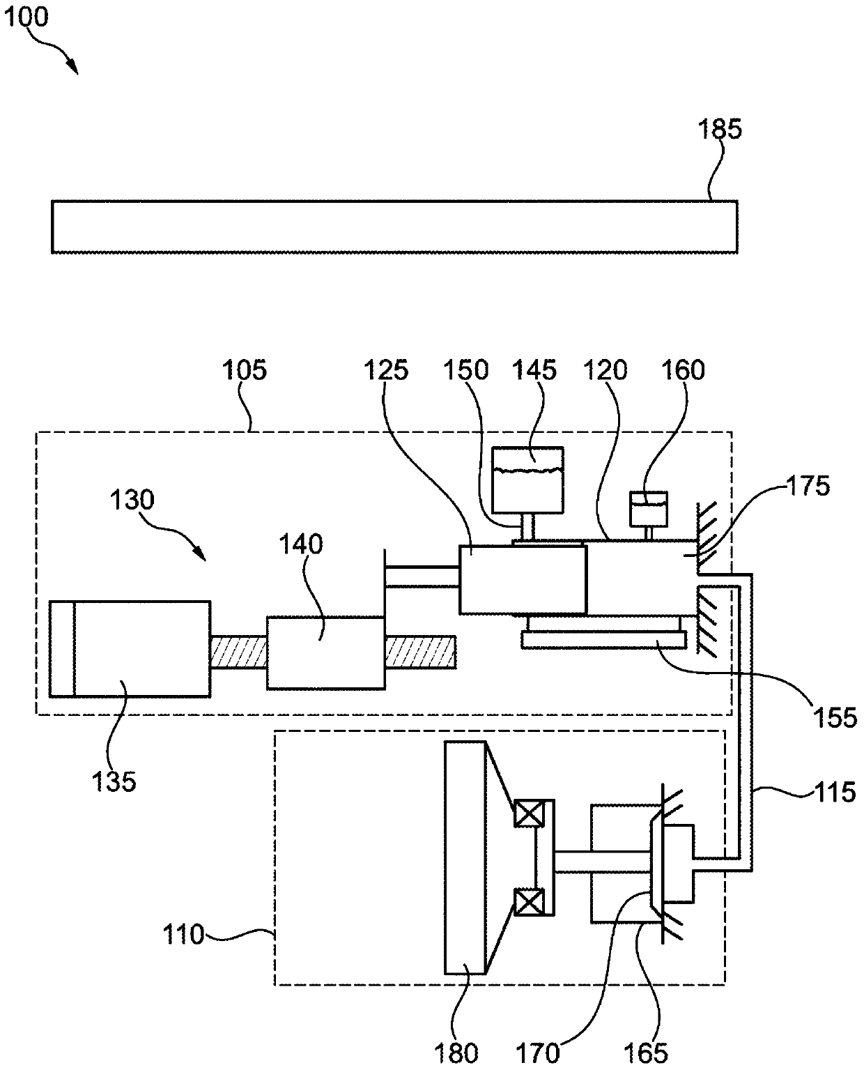
[0027] figure 1 A hydrostatic clutch actuator 100 is shown. Clutch actuator 100 includes a driving side 105 and a driven side 110 . The two sides are fluidically connected to each other by means of hydraulic lines 115 .

[0028] The active side 105 includes an active cylinder 120 which is closed by means of an active piston 125 . The active piston 125 can be moved axially in the active cylinder 120 by means of a drive 130 . The drive 130 generally includes an electric motor 135 , which is connected to the drive piston 125 by means of a switching mechanism 140 , wherein the switching mechanism 140 includes, for example, a screw drive.

[0029] In one embodiment, a compensating tank 145 is provided on the master cylinder 120 , which is filled with hydraulic fluid at ambient pressure. The connection opening 150 between the compensation container 145 and the master cylinder 120 is released by the master piston 125 when the master piston has moved far enough away from the maste...


PUM


Abstract

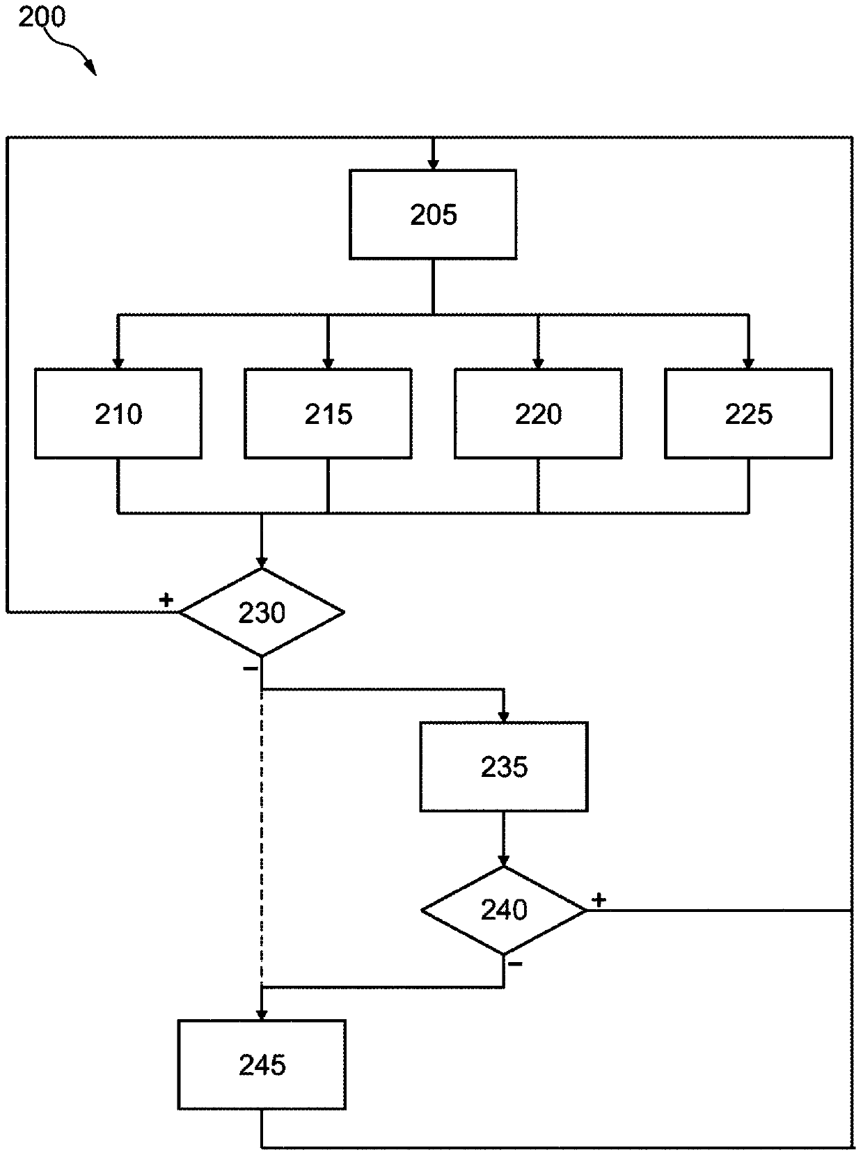
The invention relates to a coupling actuator comprising a master cylinder, a hydraulic line and a slave cylinder, for actuating a coupling. The invention also relates to a method for detecting a leakage on a coupling actuator comprising the following steps: a parameter of the coupling actuator is determined, the parameter is compared to a predetermined threshold value, if the parameter exceeds the threshold value, a warning of a leakage is provided, and the warning is communicated.

Description

technical field [0001] The invention relates to a hydraulic clutch actuator. The invention relates in particular to the detection of leakage at the clutch actuator. Background technique [0002] The hydraulic clutch actuator comprises a master cylinder and a slave cylinder, which are connected to one another via hydraulic lines. An active piston is accommodated in the active cylinder, which is axially displaceable by means of an actuator. A slave piston housed in a slave cylinder reflects this movement by exchanging hydraulic fluid between the master and slave cylinders. In this case, the driven piston is designed to actuate a clutch for transmitting torque in a drive train, in particular a drive train of a motor vehicle. In one embodiment, the clutch is closed by means of a clutch spring and the actuation causes the clutch to disengage so that no torque is transmitted through the clutch, while in another embodiment the actuation causes the friction elements of the clutch...

Claims


Application Information

Patent Timeline
Patent Type & Authority Patents(China)
IPC IPC(8): F16D48/02
CPCF16D48/02F16D2500/1026F16D2500/10412F16D2500/3023F16D2500/3026F16D2500/5016F16D2500/70404F16D2500/7041
Inventor 伊夫·贝尔廷·达斯-蒂约赫里斯蒂安·福尔布雷希特于尔根·本茨
Owner SCHAEFFLER TECH AG & CO KG
Why Eureka
Try Eureka