
Heatable hollow body

A technology of hollow body and heating layer, which is applied in pipeline heating/cooling, pipes/pipe joints/fittings, mechanical equipment, etc., which can solve problems such as difficult heat transfer, and achieve the effect of simplifying production and easy processing

Inactive Publication Date: 2016-09-07
CONTITECH
View PDF11 Cites 0 Cited by
  • Summary
  • Abstract
  • Description
  • Claims
  • Application Information

AI Technical Summary

Problems solved by technology

As a result, it is difficult to transport the heat generated by electricity to the medium inside the hollow body

Method used


Image

  • Heatable hollow body
  • Heatable hollow body
  • Heatable hollow body

Examples


Embodiment Construction

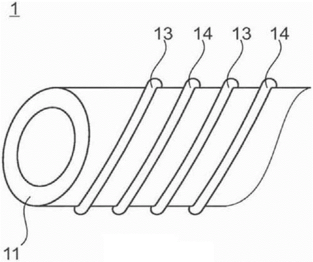
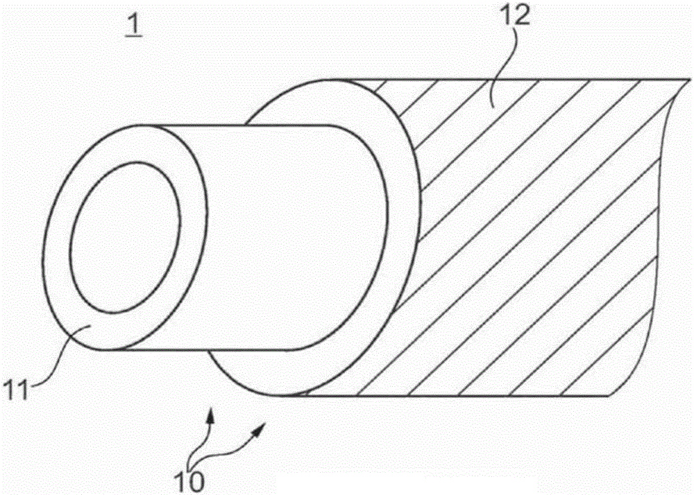
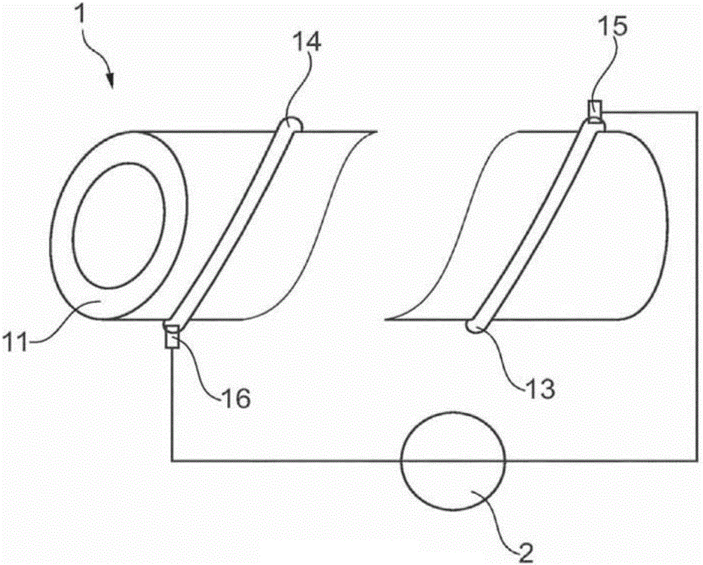
[0032] figure 1 A schematic perspective view of a heatable hollow body 1 in the form of a heatable hose 1 according to a first exemplary embodiment is shown. The heatable hose 1 has a heatable layer 11 which is the innermost layer 11 of its wall structure and as a result is completely in direct contact with the medium to be heated inside the heatable hose 1 . Around this heatable innermost layer 11 further layers (not shown) may be provided. A pair of electrodes 13, 14 in the form of a first electrical conductor 13 and a second electrical conductor 14 are arranged on the heatable layer 11 such that said electrodes pass through an electrically conductive material, such as conductive carbon black, metal powder, in an electrically conductive manner. Or carbon nanotubes are extensively linked together. If a voltage is now applied to the electrodes 13 , 14 , the galvanic heat loss of the electrically conductive material through the thus heated innermost layer 11 of the hose 1 lea...


PUM


Abstract

The present invention relates to a heatable hollow body (1) for transporting and / or storing liquid, gaseous, and / or pasty media, comprising at least one heatable layer (11) which comprises an electrically conductive material. The heatable hollow body (1) is characterized in that the heatable layer (11) is at least partly, preferably to a large extent, more preferably completely, in direct contact with the medium to be heated.

Description

technical field [0001] The invention relates to a heatable hollow body according to the preamble of claim 1 and to a system with such a heatable hollow body. Background technique [0002] In the field of hollow bodies for conveying and / or storing liquid, gaseous or pasty media, various applications are known in which these hollow bodies are electrically heatable. In this way, for example, a predetermined temperature can be reached during transport and / or during storage. Furthermore, this is important in particular when media are intended to be transported and / or stored in hollow bodies where there is a risk that said media will freeze during use, possibly preventing transport through the hollow body or from Hollow body discharge. This concerns, for example, hoses for transporting water or aqueous media. For applications for conveying and / or storing highly viscous media such as oil, it may also be advisable to reduce the viscosity of the medium by heating the medium and th...

Claims


Application Information

Patent Timeline
Patent Type & Authority Applications(China)
IPC IPC(8): F16L53/00F16L53/38F16L53/37
CPCF16L53/37F16L53/38
Inventor 斯特凡·佐斯特曼科琳娜·洛伦茨斯特芬·维茨克弗兰克·荣格里克特哈拉尔德·科赫阿列克谢·格里布沃尔弗拉姆·赫曼尼古拉·布卢姆
Owner CONTITECH
Learn More