
Device for flow direction switchover and flow control

A technology of flow control and outer ring, which is applied in the direction of valve energy absorption devices, valve devices, valve details, etc., can solve the problems of system complexity and achieve the effect of simplifying the system and reducing noise

Inactive Publication Date: 2016-09-14
NO 719 RES INST CHINA SHIPBUILDING IND
View PDF8 Cites 1 Cited by
  • Summary
  • Abstract
  • Description
  • Claims
  • Application Information

AI Technical Summary

Problems solved by technology

[0005] The purpose of the present invention is to overcome the shortcomings of the above-mentioned prior art, aiming at the problem that different valve parts need to be used for flow direction switching and flow adjustment, which leads to complex systems, and to provide a four-way valve with both flow direction switching function and flow adjustment function. port control device, which greatly simplifies the system

Method used


Image

  • Device for flow direction switchover and flow control
  • Device for flow direction switchover and flow control
  • Device for flow direction switchover and flow control

Examples


Embodiment Construction

[0022] The present invention will be further described below in conjunction with the accompanying drawings and embodiments.

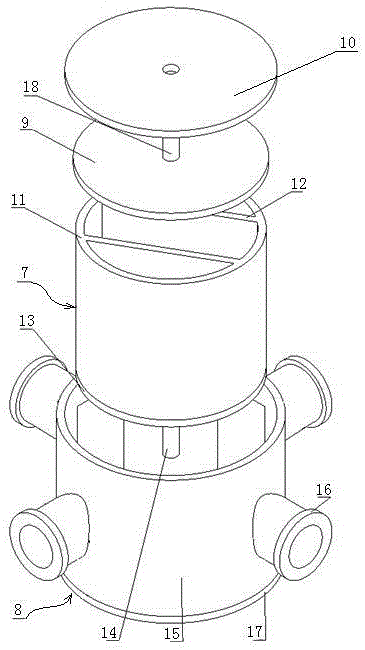
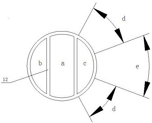
[0023] Such as figure 2 , 3 As shown, the embodiment of the present invention provides a device for flow direction switching and flow control, including a valve core 7, a four-port valve seat 8, an end cover 9 and a top cover 10; the valve core 7 is composed of an outer ring 11, a partition Plate 12, spool bottom plate 13 and spool shaft 14, the spool bottom plate 13 is fixed on the bottom of the spool, the spool shaft 14 is fixed on the spool bottom plate 13, the outer ring 11 is divided by a pair of parallel partitions into three cavities a, b, c, the first baffle and the second baffle are symmetrically distributed on both sides of the spool axis, the outer ring 11 is provided with openings, and the opening in the middle cavity a of the outer ring The holes are parallel to the first partition and the second partition, perpendicular to the axis of t...


PUM


Abstract

The invention belongs to the technical field of fluid control, and provides a device for flow direction switchover and flow control. The device comprises a valve element, a four-port valve seat, an end cover and a top cover. The valve element is composed of an outer ring, partition plates, a valve element bottom plate and a valve element shaft. The four-port valve seat is composed of a hole opening outer ring, necking components, a valve seat bottom plate and a sealing piece. The device has the following beneficial effects that firstly, flow direction switchover and flow control are achieved through a single valve, and a system is greatly simplified; secondly, a manner of diversion rather than throttling is adopted, the flow noise is controlled through the hole opening size, and noise is low; and thirdly, the device can generate constant flow resistance through the valve element hole opening arrangement, the flow resistance is equal under different work conditions and at valve rotation angles, a pump can work near a rated point, and running under a deviation work condition does not exist.

Description

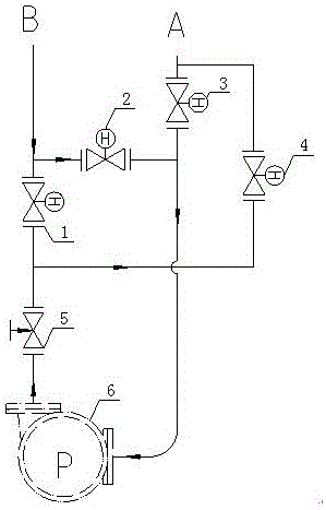
technical field [0001] The invention belongs to the technical field of fluid control, and in particular relates to a device that can be used for flow direction switching and flow control. Background technique [0002] Flow direction switching and flow control are two important functions in the fluid control system. Generally, flow direction switching is realized by multiple on-off valves on the pipeline, and flow control is realized by regulating valves. [0003] figure 1 Shown in is the traditional flow direction switching and flow control system. When supplying water from point A to point B, it is necessary to open the third on-off valve 3 and the first on-off valve 1, close the second on-off valve 2 and the fourth on-off valve 4, and adjust Valve 5 controls the flow; when water is supplied from point B to point A, the flow direction shown in the figure requires opening the second on-off valve 2 and the fourth on-off valve 4, closing the third on-off valve 3 and the first...

Claims


Application Information

Patent Timeline
Patent Type & Authority Applications(China)
IPC IPC(8): F16K11/052F16K47/02
CPCF16K11/0525F16K47/02
Inventor 秦子明俞健谢江辉蔡标华肖龙洲石兆存王晓东王楠李伟白亚鹤张德满严智远陈国锋尚进唐昉李斌胡洋胡秋旭李红信
Owner NO 719 RES INST CHINA SHIPBUILDING IND
Learn More