Dual-precision weighing sensor

A weighing sensor, double-precision technology, applied in the detailed information of weighing equipment, instruments, weighing, etc., can solve the problem of use, can not be used as other, can not be used as a weight scale, etc.

Inactive Publication Date: 2016-09-14
申俊
View PDF3 Cites 0 Cited by
  • Summary
  • Abstract
  • Description
  • Claims
  • Application Information

AI Technical Summary

Problems solved by technology

[0002] The weight electronic scales currently on the market are mainly composed of a loading board, a display screen, an adjustment button, a power module and a load cell for supporting the loading board. When the weight of the loaded object exceeds the preset value, the display screen will start to display the value. The preset value is generally 5 kg; in addition, the maximum range of this kind of weight electronic scale is generally 180 kg, and the accuracy value is only 100 grams. The error is large. Therefore, this traditional weight electronic scale can basically not be used for other purposes except for weighing, especially it cannot be used as a kitchen electronic scale.
However, the existing kitchen electronic scales have an accuracy of 1 gram or even less, but their range generally does not exceed 10 kilograms, so they cannot be used as weighing scales.

Method used


Image

  • Dual-precision weighing sensor
  • Dual-precision weighing sensor
  • Dual-precision weighing sensor

Examples


Embodiment 1

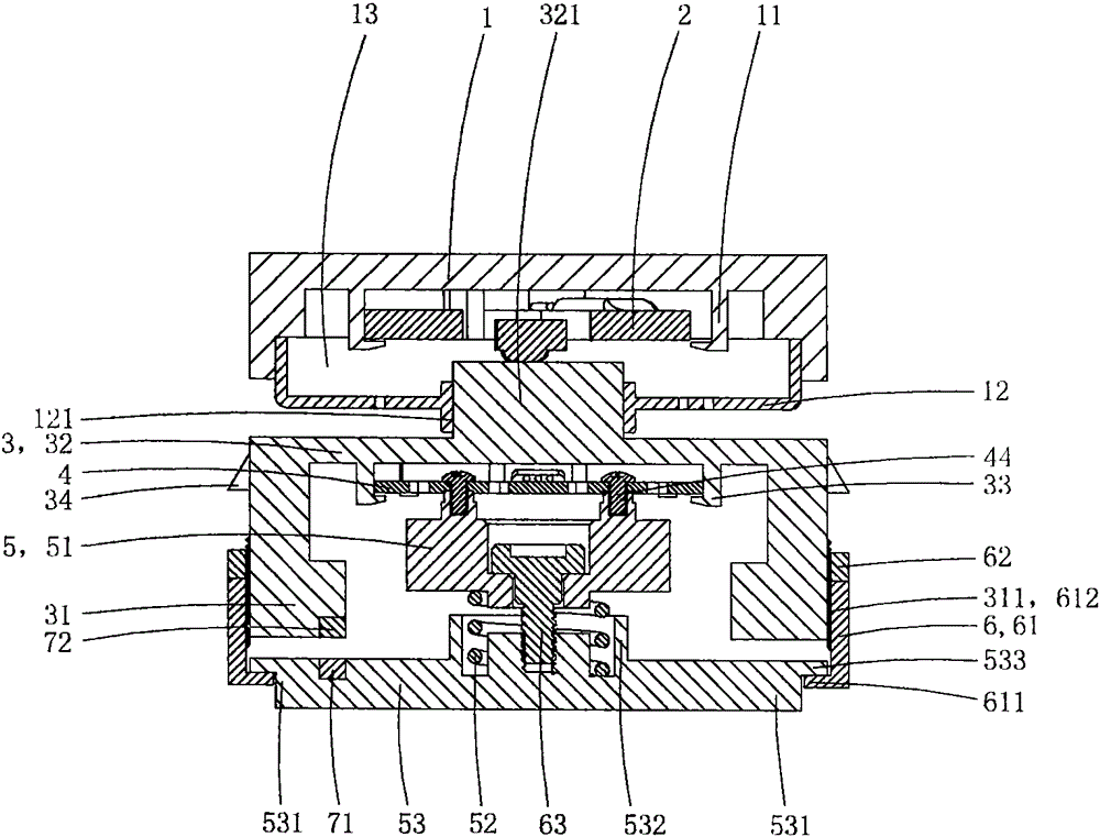
[0028] This embodiment is a double precision load cell, see Figure 1 to Figure 6 As shown, it includes the first mounting base 1, the first precision load cell 2, the second mounting base 3, the second precision load cell 4 and the elastic support 5 which are sequentially crimped; the elastic support includes an upper support 51 , Thread spring 52 and lower support 53. The top end of the spring abuts on the upper supporting member, and the bottom end of the elastic supporting member abuts on the lower supporting member; the lower supporting member is provided with a force guiding support portion 531 .

[0029] The bottom wall of the first mounting seat is provided with a first card seat 11, and the top wall of the first mounting seat has a plane for bonding and fixing on the bottom wall of the external loading plate; the first precision load cell is provided with The first fixed part 21, the first force-bearing deformation part 22 and the first resistance strain gauge 23 arr...

Embodiment 2

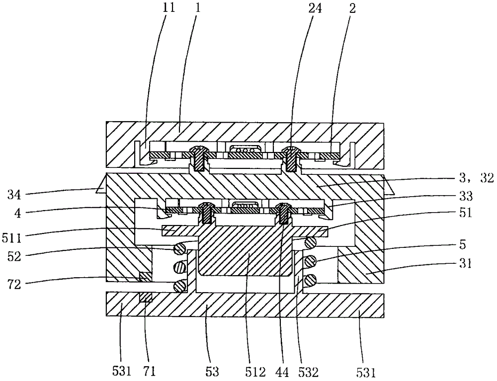
[0049] This embodiment is basically the same as the above-mentioned embodiment 1, the difference is: see Figure 7 to Figure 8 As shown, this embodiment also includes an adjustment mechanism 6 for adjusting the overall height of the elastic support; the outer peripheral wall of the lower support is provided with an outwardly convex stopper 533, and the outer peripheral wall of the force-guiding crimping part is provided with an outer Threaded area 311; the adjustment mechanism includes an adjustment screw cap 61 and a top screw cap 62, the inner wall of the lower part of the adjustment screw cap is provided with an inwardly convex annular anti-off crimping part 611, and the inner wall of the upper part is provided with a guide force crimping part. The internal thread area 612 adapted to the external thread area; the anti-off crimping portion is sleeved on the outer peripheral wall of the lower support member below the stopper portion, and the top screw cap is also screwed on th...

Embodiment 3

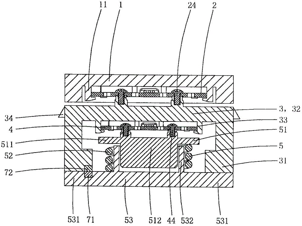
[0052] This embodiment is basically the same as the above-mentioned embodiment 2, the difference is: see Figure 9 to Figure 12As shown, the first precision load cell in this embodiment is still provided with a first fixing part, a first force-bearing deformation part, and a sensor set on the first force-bearing deformation part for detecting the deformation amount of the first force-bearing deformation part. The first resistance strain gauge; but the shape of the first precision load cell in this embodiment is similar to the reverse "G" shape, its first fixed part is similar to "C" shape, and the shape of the first force-bearing deformation part is similar to A smaller "C" shape is connected with the first fixed part to form a reverse "G" shape. The measuring range and accuracy of this first precision load cell are the same as those in Embodiment 1, and this structure can also be made by stamping, and its manufacturing process is simpler. The bottom of the first mounting sea...


PUM


Abstract

Disclosed in the invention is a dual-precision weighing sensor comprising a first mounting seat, a first precision weighing sensor, a second mounting seat, a second precision weighing sensor and an elastic supporting element. The first mounting seat, the first precision weighing sensor, the second mounting seat, the second precision weighing sensor and the elastic supporting element are arranged successively in a pressing mode. The elastic supporting element consists of an upper support element, a spring, and a lower support element; the top of the spring is abutted against the upper support element and the bottom of the elastic supporting element is abutted against the lower support element. A guiding and pressing part is arranged at the second mounting seat; and a guiding and supporting part is arranged at the lower supporting element. In a free state, the guiding and pressing part is higher than the guiding and supporting part. When a force is exerted on the second mounting seat, the second precision weighing sensor presses the spring and thus the guiding and pressing part is driven to move down; and when the force exerted on the second mounting seat reaches a preset degree, the guiding and pressing part moves down and then presses the guiding and supporting part. The weighing sensor has the continuous dual-step ranges and has different precision values in ranges at all steps.

Description

technical field [0001] The invention belongs to the technical field of weighing sensor structure design, and in particular relates to a double-precision weighing sensor. Background technique [0002] The weight electronic scales currently on the market are mainly composed of a loading board, a display screen, an adjustment button, a power module and a load cell for supporting the loading board. When the weight of the loaded object exceeds the preset value, the display screen will start to display the value. The preset value is generally 5 kg; in addition, the maximum range of this kind of weight electronic scale is generally 180 kg, and the accuracy value is only 100 grams. The error is large. Therefore, this traditional weight electronic scale can not be used for other purposes except weighing the body on weekdays, especially it cannot be used as a kitchen electronic scale. And existing kitchen electronic scale, its precision value can reach 1 gram even smaller, but its me...

Claims


Application Information

Patent Timeline
Patent Type & Authority Applications(China)
IPC IPC(8): G01G19/50G01G21/23
CPCG01G19/50G01G21/23
Inventor 申俊
Owner 申俊
Why Eureka
Try Eureka