Display device and manufacturing method thereof

一种显示装置、制造方法的技术,应用在光学、仪器、电数字数据处理等方向

Active Publication Date: 2016-09-14
TIANMA MICRO ELECTRONICS CO LTD
View PDF9 Cites 10 Cited by
  • Summary
  • Abstract
  • Description
  • Claims
  • Application Information

AI Technical Summary

Problems solved by technology

Therefore, the OCR50 leaks out to the back of the display panel 10

Method used


Image

  • Display device and manufacturing method thereof
  • Display device and manufacturing method thereof
  • Display device and manufacturing method thereof

Examples


Embodiment Construction

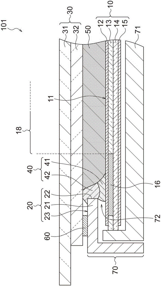
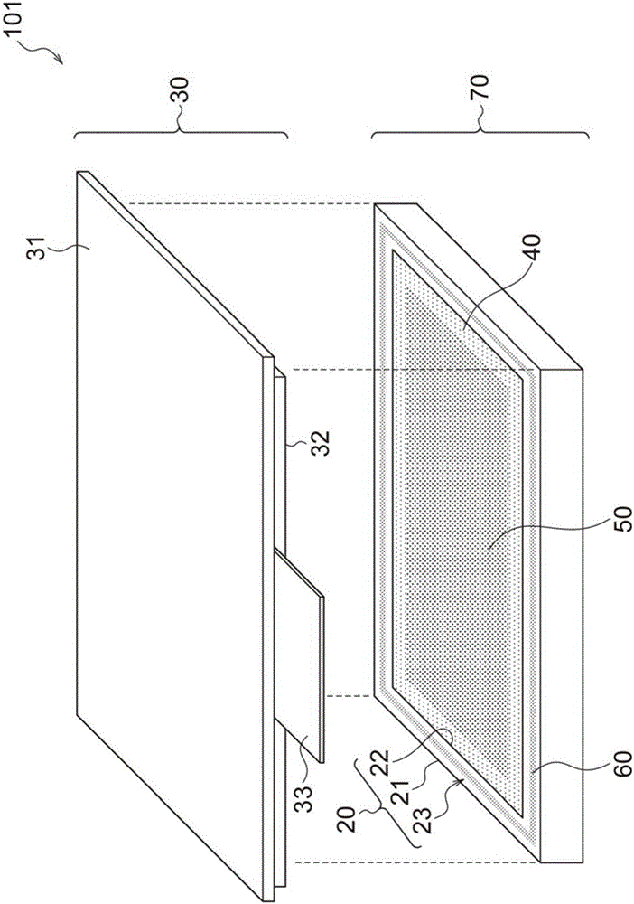
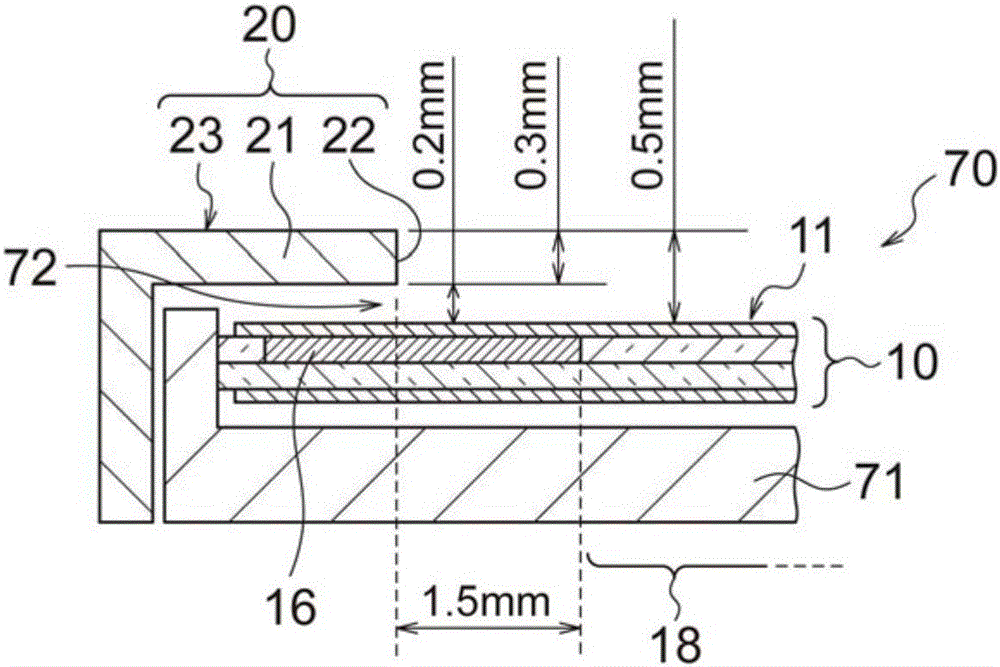
[0049] Hereinafter, modes for implementing the present invention (hereinafter, referred to as “exemplary embodiments”) will be described with reference to the drawings. In this specification and the drawings, even if there is a slight difference between structural elements, the same reference numerals are used to designate substantially the same structural elements. The shapes in the drawings are shown for easy understanding by those skilled in the art, and thus the dimensions and ratios thereof do not necessarily match the actual dimensions and ratios. The cross-sectional view only shows the cross-section, and its depth structure is omitted. "Comprising" in the scope of the present specification and claims also includes the case of having elements other than those described therein. The same goes for "has", "comprises" and the like.

[0050] First, refer to Figure 23 to Figure 25C A display device of related art 3 that is the basis of the present invention will be describ...


PUM


Abstract

The invention refers to a display device and a manufacturing method thereof. To provide a display device of high quality and high reliability by securely sealing the gap between the bezel and the display panel even when variation is generated in the gap. The display device includes: a display panel including a display face; a bezel which includes a frame part and an aperture end that is on the inner side of the frame part, and covers the fringe of the display panel on the display face side by the frame part; a frontal panel provided by sandwiching the bezel on the display face side of the display panel; and a resin member provided along the whole circumference of the aperture end of the bezel. The resin member has a first resin member formed on the display face and a second resin member formed to cover over the first resin member and a surface of the bezel opposing to the frontal panel.

Description

[0001] Cross References to Related Applications [0002] This application is based upon and claims the benefit of priority from Japanese Patent Application No. 2015-045078 filed on Mar. 6, 2015, the entirety of which is incorporated herein by reference. technical field [0003] The present invention relates to a display device such as a liquid crystal display device, and a method of manufacturing the same. Background technique [0004] In recent years, the number of display devices each having a front panel such as a touch panel or a decorative panel on a liquid crystal display module as a display device has been increasing. The touch panel is an input interface component. Decorative panels are tempered glass, etc. that are printed for decoration in terms of design quality and protection of the display surface. [0005] When the front panel is loaded on the liquid crystal display module, generally, an air layer exists between the surface of the liquid crystal panel and th...

Claims


Application Information

Patent Timeline
Patent Type & Authority Applications(China)
IPC IPC(8): G02F1/1333G06F3/041G06F3/044
CPCG02F1/1333G02F1/133308G02F1/13338G06F3/041G06F3/044G06F2203/04103G02F1/1341G06F1/1601G06F1/1637G06F2200/1612
Inventor 藤田明中西太吉田仁铃木昭
Owner TIANMA MICRO ELECTRONICS CO LTD
Why Eureka
Try Eureka