Displacement state recognition device for automatic sweeper

A state recognition and sweeping machine technology, which is applied to manual sweeping machines, carpet cleaning, floor cleaning, etc., can solve the problems of judging trace wear and making mistakes easily

Inactive Publication Date: 2016-09-21
JIAXING J CREATION INTELLIGENT ELECTRIC APPLIANCE CO LTD
View PDF6 Cites 8 Cited by
  • Summary
  • Abstract
  • Description
  • Claims
  • Application Information

AI Technical Summary

Problems solved by technology

At present, the detection of whether the automatic sweeper is in a stuck state usually uses a light sensor, which detects the change of the driven wheel, and the judgment marks on the driven wheel will be worn after a long time of use, and the judgment at this time is very easy. go wrong

Method used


Image

  • Displacement state recognition device for automatic sweeper
  • Displacement state recognition device for automatic sweeper
  • Displacement state recognition device for automatic sweeper

Examples


Embodiment 1

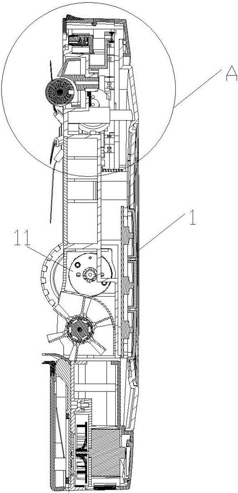
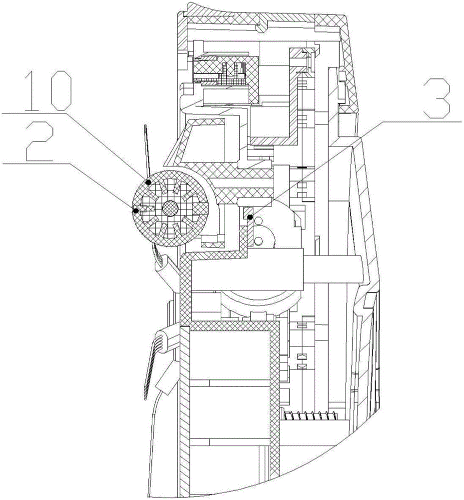
[0021] see figure 1 , 2 And 5, a displacement state identification device for an automatic sweeper described in this embodiment, the automatic sweeper 1 includes: a driven wheel 10 that rolls as the automatic sweeper 1 moves, and the driven wheel 10 is in contact with the ground; a power Wheel 11, the power wheel 11 drives the automatic sweeper 1 to move; in addition, it also includes: a magnet 2 and a Hall induction sheet 3; the position distance between a magnet 2 and a Hall induction sheet 3 changes with the rotation of the driven wheel 10, the The Hall induction sheet 3 induces the transformation of the position distance of the magnet 2 .

[0022] A magnet 2, the magnet 2 is fixedly installed on the driven wheel 10, and changes position as the driven wheel 10 rotates; a Hall sensor 3 is arranged adjacent to the driven wheel 10, and the Hall sensor 3 is installed on the shell of the automatic sweeper 1. According to the information of the position change of the magnet 2 i...

Embodiment 2

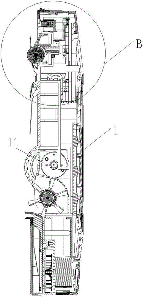
[0029] see Figures 3 to 5 , a displacement state identification device for an automatic sweeper described in this embodiment, the automatic sweeper 1 includes: a driven wheel 10 that rolls along with the movement of the automatic sweeper 1, the driven wheel 10 is in contact with the ground; a power wheel 11 , the power wheel 11 drives the automatic sweeper 1 to move; in addition, it also includes: a magnet 2 and a Hall induction sheet 3; the position distance between the magnet 2 and a Hall induction sheet 3 changes with the rotation of the driven wheel 10, and the Hall The induction sheet 3 induces the transformation of the position distance of the magnet 2 .

[0030] In this embodiment, a Hall sensor 3 is installed on the driven wheel 10, and changes its position as the driven wheel 10 rotates;

[0031] According to the information of the position change of the magnet 2 induced by the Hall induction sheet 3, it is judged whether the automatic sweeper 1 is still moving.

...


PUM


Abstract

The invention relates to a displacement state recognition device for an automatic sweeper. The automatic sweeper comprises a driven wheel, a power wheel, a magnet and a Hall sensor. The driven wheel rolls along with movement of the automatic sweeper and contacts with the ground; the power wheel drives the automatic sweeper to move; a positional distance between the magnet and the Hall sensor varies along with rotation of the driven wheel, and the Hall sensor senses changes of positional distance of the magnet.

Description

technical field [0001] The invention relates to a displacement state recognition device for an automatic sweeper. Background technique [0002] The automatic sweeper is an automatic cleaning device that automatically detects the area to be cleaned and obstacles under unmanned control. The automatic sweeper is often trapped by obstacles during cleaning. This time, the automatic sweeper needs to change the original operating state or start to get out of trouble. model. At present, the detection of whether the automatic sweeper is in a stuck state usually uses a light sensor, which detects the change of the driven wheel, and the judgment marks on the driven wheel will be worn after a long time of use, and the judgment at this time is very easy. error. Contents of the invention [0003] The purpose of the present invention is to overcome the above-mentioned deficiencies in the prior art, and provide a displacement state identification device for an automatic sweeper that can...

Claims


Application Information

Patent Timeline
Patent Type & Authority Applications(China)
IPC IPC(8): A47L11/24A47L11/40
CPCA47L11/24A47L11/4002A47L11/4061A47L2201/04
Inventor 李敬
Owner JIAXING J CREATION INTELLIGENT ELECTRIC APPLIANCE CO LTD
Why Eureka
Try Eureka