Dust removal mesh welding device and dust removal mesh welding method

A technology of welding device and dust removal net, which is applied to other manufacturing equipment/tools, manufacturing tools, etc., can solve the problems of time-consuming and laborious, inconvenient mechanical grinding, and affecting the dust removal effect.

Active Publication Date: 2016-09-21
河北骄阳焊工有限公司
View PDF7 Cites 10 Cited by
  • Summary
  • Abstract
  • Description
  • Claims
  • Application Information

AI Technical Summary

Problems solved by technology

Because the horizontal wire is relatively thin, if the method of ordinary welding wire mesh is adopted, the horizontal wire is placed in the hopper, and the ordinary wire gripper is used to grip the wire. After the wire is gripped, the horizontal wire falls along the slide, and the horizontal wire is easy to tilt, causing If they are not parallel to each other, it will greatly affect the dust removal effect; if the method of directly cutting and welding the horizontal wires is used, after the welding is completed, both ends of the horizontal wires need to be polished. Due to the short distance between the horizontal wires, it is not convenient for mechanical grinding, and manual grinding is not only time-consuming Laborious, and the grinding quality is poor; affect the dust removal effect

Method used


Image

  • Dust removal mesh welding device and dust removal mesh welding method
  • Dust removal mesh welding device and dust removal mesh welding method
  • Dust removal mesh welding device and dust removal mesh welding method

Examples


Embodiment Construction

[0041] The structure and operating principle of the dust removal net welding device and the method for welding the dust removal net according to the present invention will be further described in detail below in conjunction with the accompanying drawings and specific embodiments.

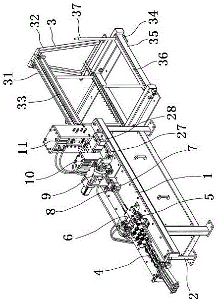
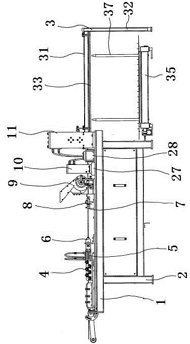
[0042] Such as figure 1 and figure 2 As shown, the structural diagram of the dust removal net welding device of the present invention, the dust removal net welding device of the present invention includes a frame 2 with an operating platform 1 and a material receiving frame 3 located behind the frame, and is arranged on the operating platform 1 near the front There is a straightening mechanism 4, and behind the straightening mechanism 4, a wire-pushing sleeve 6 connected to the wire-feeding cylinder 5 is arranged. Behind the wire-pushing sleeve 6, a threading frame 8 with a threading hole 7 is arranged. A welding mechanism 9 is provided, a horizontal wire bending mechanism 10 is arranged behind th...


PUM


Abstract

The invention belongs to the technical field of welding machines and dust removal mesh welding methods and discloses a dust removal mesh welding device and a dust removal mesh welding method. The dust removal mesh welding device is mainly characterized by comprising a straightening mechanism, a wire pushing sleeve, a threading rack, a welding mechanism and a transverse wire bending mechanism, which are arranged on an operation platform, wherein a lateral wire baffle is arranged on one side of a wire holding disc; a lower wire baffle is movably fixed below the lateral wire baffle through a fixing pin; a propping spring is arranged between the lower wire baffle and the lateral wire baffle; two lower welding heads are arranged on the operation platform and located on two sides below the wire holding disc; a swinging passage for allowing the lower wire baffle to swing in is formed between the two welding heads; two down-pressing air cylinders with down-pressing plates are arranged on the operation platform and located on the outer sides of two welding head seats; the opposite side surfaces of the two down-pressing plates cling to the side surfaces of the wire holding disc; and an upper welding head is located below the down-pressing plates. According to the invention, transverse wires are pressed down by the down-pressing plates, the contact and welding positions of longitudinal wires and the transverse wires are close to the outer sides of wire holding grooves, the contact positions of the longitudinal wires and the transverse wires are accurate, and the welding quality is high.

Description

technical field [0001] The invention belongs to the technical field of a welding machine and a method for welding a dust removal net, and in particular relates to a welding device for a dust removal net and a method for welding a dust removal net. Background technique [0002] In places such as workshops where the dust is relatively large, in order to reduce dust, it is necessary to use an energized dust removal net for dust removal. The dust is adsorbed on the dust removal net, and then the dust falls into the dust removal channel after vibration. The dust removal net adopts two filaments and a horizontal wire between the two filaments, and the end of the horizontal wire has a bend. For discharge needs, both ends of the horizontal wire are conical. Because the horizontal wire is relatively thin, if the method of ordinary welding wire mesh is adopted, the horizontal wire is placed in the hopper, and the ordinary wire gripper is used to grip the wire. After the wire is gripp...

Claims


Application Information

Patent Timeline
Patent Type & Authority Applications(China)
IPC IPC(8): B23P23/04B23P15/00
CPCB23P15/00B23P23/04
Inventor 张中盼周志成
Owner 河北骄阳焊工有限公司
Why Eureka
Try Eureka