Grinding device for end part of material pushing rod on mould

A push rod and mold technology, which is applied in the direction of grinding machine parts, grinding machines, manufacturing tools, etc., can solve problems such as inconvenient grinding processing.

Inactive Publication Date: 2016-09-21
WUJIANG HYDRAULIC COMPONENTS FOUNDRY
View PDF8 Cites 4 Cited by
  • Summary
  • Abstract
  • Description
  • Claims
  • Application Information

AI Technical Summary

Problems solved by technology

The grinding device is inconvenient to g

Method used


Image

  • Grinding device for end part of material pushing rod on mould

Examples


Embodiment Construction

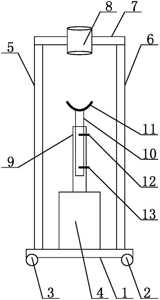
[0012] In order to make the technical means, creative features, goals and effects achieved by the present invention easy to understand, the present invention will be further described below in conjunction with specific embodiments.

[0013] Such as figure 1 As shown, a grinding device for the end of a pusher rod on a mold includes a bottom plate 1, a first support shaft 2 and a second support shaft 3 are provided at the bottom of the bottom plate 1, and the first support shaft 2 is arranged at the bottom of one end of the bottom plate 1 , the second support shaft 3 is arranged at the bottom of the other end of the base plate 1; the first support shaft 2 and the second support shaft 3 are arranged in parallel; the base plate 1 is provided with a grinding motor 4, and the base plate 1 is provided with a first side plate 5 and The second side plate 6, the first side plate 5 and the second side plate 6 are vertically arranged, the first side plate 5 is arranged on one side of the ...


PUM


Abstract

The invention discloses a grinding device for an end part of a material pushing rod on a mould. The grinding device comprises a bottom plate, wherein a grinding motor is arranged on the bottom plate; a first side plate and a second side plate are arranged on the bottom plate; the first side plate is arranged at one side of the grinding motor; the second side plate is arranged at the other side of the grinding motor; a top plate which is horizontally arranged between the end part of the first side plate and the end part of the second side plate; a guide tube which is vertically arranged is arranged on the top plate; the upper part of the grinding motor is provided with a rotary tube; a rotary shaft is arranged in the rotary tube in a sleeved manner; the outer surface of the rotary shaft is provided with outer threads; the inner surface of the rotary tube is provided with inner threads; the rotary shaft is connected with the rotary tube through threads; the upper end of the rotary shaft is provided with a grinding plate which is horizontally arranged; and the guide tube is arranged above the grinding plate. The grinding device is used for conveniently grinding the head part of the material pushing rod on the mould.

Description

technical field [0001] The invention relates to a grinding device, in particular to a grinding device for the end of a push rod on a mould. Background technique [0002] In the prior art, patent ZL201310389539.6 discloses a grinding device, which includes a sliding seat, a sliding device capable of sliding along the sliding seat, and a sander detachably mounted on the sliding device, so The sander includes a sanding sheet for sanding the surface to be sanded. The grinding device is not convenient for grinding the end of the push rod on the mould. Contents of the invention [0003] Aiming at the deficiencies in the prior art, the invention provides a grinding device for the end of the push rod on the mold, which is convenient for grinding the head of the push rod of the mold. [0004] In order to achieve the above object, the present invention is achieved through the following technical solutions: [0005] A device for grinding the end of a push rod on a mold, comprising...

Claims


Application Information

Patent Timeline
IPC IPC(8): B24B19/20B24B41/02B24B41/00
CPCB24B19/20B24B41/00B24B41/02
Inventor 浦巧生
Owner WUJIANG HYDRAULIC COMPONENTS FOUNDRY
Why Eureka
Try Eureka