Automatic feeding device for firefighting nozzle locking fasteners

A technology of automatic feeding and locking, which is used in vibration conveyors, conveyors, transportation and packaging, etc., which can solve the problems of time-consuming and laborious, complicated work process, and inability to realize mechanization.

Active Publication Date: 2016-09-21
FUJIAN NANAN GUANGWEI FIRE FIGHTING EQUIP CO LTD
View PDF9 Cites 1 Cited by
  • Summary
  • Abstract
  • Description
  • Claims
  • Application Information

AI Technical Summary

Problems solved by technology

[0003] Among them, the glass tube sprinkler head includes a sprinkler head, a nozzle seat, a glass tube, a splash plate, a seal, and a locking member. Balance body; the glass tube is filled with an organic solution with a high thermal expansion coefficient. At room temperature, the shell of the glass tube can bear a certain supporting force to ensure the sealing performance of the nozzle. Broken, the seal loses its support and is washed away by the water flow, thus starting to spray fire; however, since the glass tube has a round head of the glass tube combined with the locking piece and a pointed glass tube combined with the sealing piece, and the two ends of the locking piece The concave spherical surface combined with the round head of the glass tube and the sinking groove for screwdriver insertion are respectively formed. The seal has a groove combined with the tip of the glass tube; in order to ensure the tight assembly of the glass tube, the locking piece and the sealing piece, the

Method used


Image

  • Automatic feeding device for firefighting nozzle locking fasteners
  • Automatic feeding device for firefighting nozzle locking fasteners
  • Automatic feeding device for firefighting nozzle locking fasteners

Examples


Embodiment Construction

[0041] In order to further explain the technical solution of the present invention, the present invention will be described in detail below through specific examples.

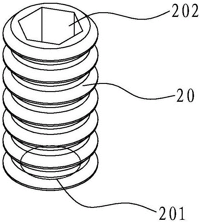
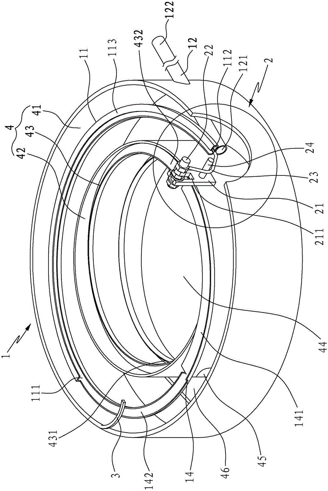
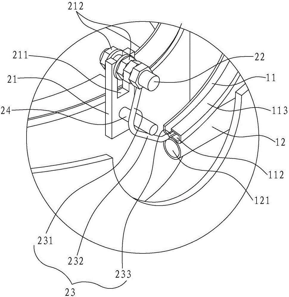
[0042] see Figure 1 to Figure 3 , the present invention discloses an automatic feeding device for a fire sprinkler locking member. The two ends of the locking member 20 are respectively formed with a concave spherical surface 201 combined with a glass tube round head and a sinking groove 202 for screwdriver insertion; the automatic feeding device It includes a vibrating discharge tray 4 for vibrating discharge, a conveying mechanism 1 for conveying the locking member 20 to the nozzle seat, and a screening mechanism 2 for screening the conveying direction of the locking member 20;

[0043] The vibrating discharge tray 4 includes an outer ring shell 41, an inner ring shell 42 and an annular conveying track 43, the outer ring shell 41 is located at the outer ring of the inner ring shell 42, the outer ring shell 4...


PUM


Abstract

Disclosed is an automatic feeding device for firefighting nozzle locking fasteners. One locking fastener is conveyed to a first conveying rail in a vibration mode through a vibration discharging plate, is conveyed to a first discharging end opening and pushes a transverse section. When a sinking groove of the locking fastener faces forwards, the end of the transverse section is inserted into the sinking groove and drives the locking fastener to be pushed by the later locking fastener to move away from the first discharging end opening. When a steel strip drives the locking fastener to return towards the first discharging end opening, the locking fastener gradually gets away from the transverse section under the action of gravity. When the locking fastener abuts against a second feeding end opening, the locking fastener can get away from the transverse section and enter a second conveying pipeline, and the steel strip continues to move towards the first discharging end opening, so that the locking fastener keeps the conveying direction that the sinking groove is backward in the second conveying pipeline all the time. When a concave spherical surface of the locking fastener faces forwards, the end of the transverse section can not be inserted onto the concave spherical surface, so that the locking fastener is pushed by the later locking fastener and gets away from the first discharging end opening, the steel strip moves towards the first discharging end opening and abuts against the first discharging end opening, and the next locking fastener is screened.

Description

technical field [0001] The invention relates to a feeding device, in particular to an automatic feeding device for fire sprinkler locking parts. Background technique [0002] In the fire automatic fire extinguishing system, the fire sprinkler is one of the patron saints of people's life and property. It is responsible for the two missions of monitoring the fire and implementing fire fighting. It is mainly used in light and medium dangerous places and commercial places, such as banks and hotels. , shopping centers, etc. There are many kinds of existing fire sprinkler heads, and there are glass tube sprinkler heads and fusible element sprinkler heads according to the classification of heat sensitive elements. [0003] Among them, the glass tube sprinkler head includes a sprinkler head, a nozzle seat, a glass tube, a splash plate, a seal, and a locking member. Balance body; the glass tube is filled with an organic solution with a high thermal expansion coefficient. At room te...

Claims


Application Information

Patent Timeline
IPC IPC(8): B65G27/02B65G27/34
CPCB65G27/02B65G27/34
Inventor 陈文杰
Owner FUJIAN NANAN GUANGWEI FIRE FIGHTING EQUIP CO LTD
Why Eureka
Try Eureka