Cutting equipment for cloth bag production

A cutting and equipment technology, applied in the cutting of textile materials, bag making operations, paper/cardboard containers, etc., can solve problems such as inappropriate setting of cutting mechanism, uneven incision, and cloth jamming

Active Publication Date: 2021-05-18
南京中隐客归网络科技有限公司
View PDF7 Cites 2 Cited by
  • Summary
  • Abstract
  • Description
  • Claims
  • Application Information

AI Technical Summary

Problems solved by technology

[0003] Cloth cutting machine is a kind of machine that cuts cloth and is mainly used to cut a large number of small-sized samples or products. However, most of the existing cloth cutting devices will cause uneven cuts and cloth jams due to improper cutting mechanism settings. live, there is a security risk

Method used


Image

  • Cutting equipment for cloth bag production
  • Cutting equipment for cloth bag production
  • Cutting equipment for cloth bag production

Examples


Embodiment 1

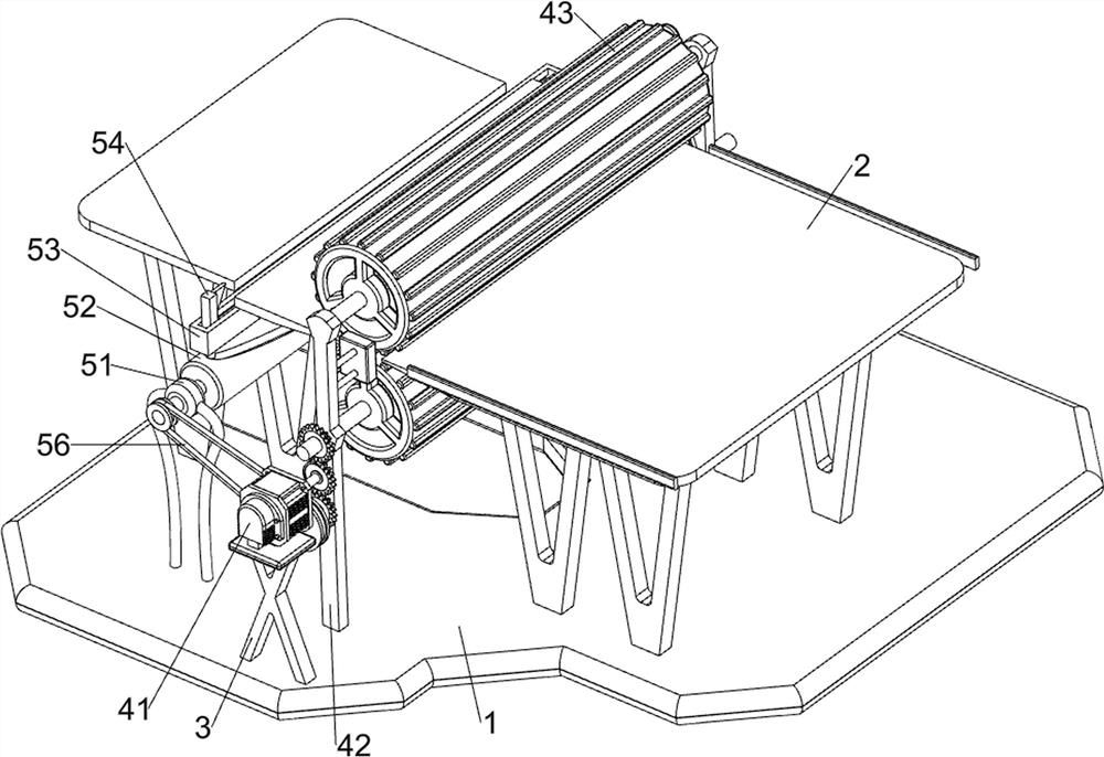
[0079] A cutting device for cloth bag production, such as figure 1 As shown, it includes a base 1, a workbench 2, a support 3, a transmission mechanism 4 and a cutting mechanism 5. Two workbenches 2 are connected to the upper side of the base 1, a support 3 is connected to the upper side of the base 1, and a support 3 is connected to the upper side of the support 3. The transmission mechanism 4 is connected with a cutting mechanism 5 on the upper side of the base 1 .

[0080] When the device needs to be used, the user can place the cloth on the upper side of the workbench 2, so that the cloth passes through the transmission mechanism 4, and starts the transmission mechanism 4 to rotate forward. The cloth moves to the left. When the transmission mechanism 4 rotates to the inside without contact, the cloth stops moving, so as to achieve the purpose of automatic transmission of the cloth and automatic feeding. When the transmission mechanism 4 rotates forward to contact with the ...

Embodiment 2

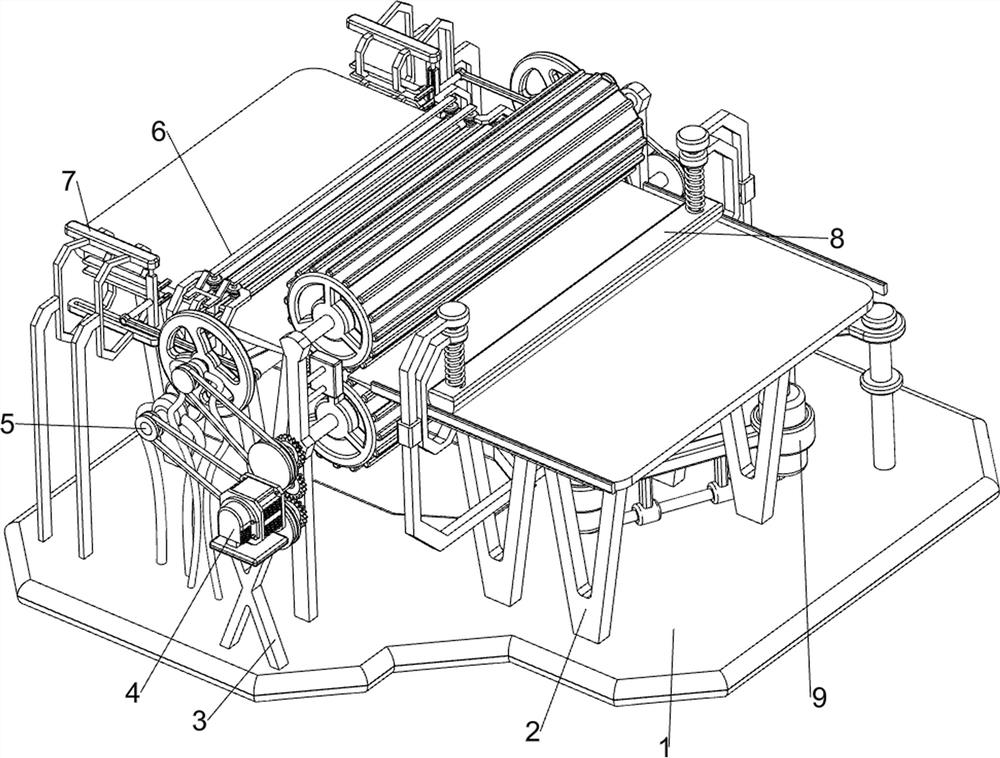
[0082] On the basis of Example 1, such as figure 2 and image 3 As shown, the transmission mechanism 4 includes a servo motor 41, a mounting plate 42, a transmission cylinder 43, a first full gear 44, a missing gear 45, a rotating shaft 46, a gear set 47, a first belt transmission assembly 48 and a block 49, and the bracket 3 The upper side is connected with a servo motor 41, the front and rear sides of the upper part of the base 1 are connected with a mounting plate 42, two transmission cylinders 43 are connected in rotation between the mounting plates 42, and the first full gear 44 is connected to the transmission cylinder 43 below, the servo A missing gear 45 is connected to the output shaft of the motor 41, and the missing gear 45 is meshed with the first full gear 44. A rotating shaft 46 is connected to the rear mounting plate 42 in a rotational manner, and a gear set 47 is connected between the upper transmission cylinder 43 and the rotating shaft 46. A first belt tran...


PUM


Abstract

The invention relates to cutting equipment, and especially relates to cutting equipment for cloth bag production. The invention aims at providing the cutting equipment for cloth bag production, enabling a cloth notch to be smooth, realizing automatic cloth conveying, and reducing potential safety hazards. The cutting equipment for cloth bag production comprises a base, workbenches, a support, a transmission mechanism and a cutting mechanism, wherein the two workbenches are connected to the top side of the base; the support is connected to the top side of the base; the transmission mechanism is connected to the top side of the support; and the cutting mechanism is connected to the top side of the base. According to the invention, through cooperation of a servo motor, a conveying cylinder, a tooth-missing gear and a first belt conveying assembly, automatic cloth conveying is achieved, and the purpose of automatic loading is realized.

Description

technical field [0001] The invention relates to a cutting device, in particular to a cutting device for cloth bag production. Background technique [0002] Cloth is a commonly used material in decorative materials, including chemical fiber carpets, non-woven wall coverings, linen cloth, nylon cloth, colored tape and flannel. The main force that cannot be ignored in the sales space, extensive use of fabrics for wall partitions and background treatment can also form a good commercial space display style. [0003] Cloth cutting machine is a kind of machine that cuts cloth and is mainly used to cut a large number of small-sized samples or products. However, most of the existing cloth cutting devices will cause uneven cuts and cloth jams due to improper cutting mechanism settings. Live, there is a security risk. Contents of the invention [0004] In order to overcome the shortcomings of uneven incision and cloth jamming, the purpose of the present invention is to provide a cu...

Claims


Application Information

Patent Timeline
Patent Type & Authority Applications(China)
IPC IPC(8): B26D7/02B26D7/08B31B70/20D06H7/00
CPCB26D7/015B26D7/025B26D7/08D06H7/00B31B70/20
Inventor 刘小婷
Owner 南京中隐客归网络科技有限公司
Why Eureka
Try Eureka