A self-cleaning oil pipeline connection flange

A technology for oil pipelines and connecting flanges, which is applied in the field of self-cleaning oil pipeline connecting flanges, can solve problems such as oil pipeline blockage, and achieve the effects of improving production efficiency and being beneficial to use.

Active Publication Date: 2018-09-11
浙江大业法兰有限公司
View PDF5 Cites 0 Cited by
  • Summary
  • Abstract
  • Description
  • Claims
  • Application Information

AI Technical Summary

Problems solved by technology

[0002] Nowadays, with the continuous development of human civilization, the continuous innovation of industrial level, and the continuous improvement of oil extraction technology, the longest problem encountered in the process of oil extraction is the transmission problem encountered in the process of oil extraction. In the prior art, pipelines are usually used for oil extraction. It can be seen that the requirements for oil transmission pipelines are relatively high in the process of oil extraction, and the selection of connectors for oil transmission pipelines is also important during the transmission process. Pipeline connectors are usually connected by flanges. In the existing oil pipeline connection flanges, it is usually aimed at the connection between two pipelines, and oil pipelines usually form oil at the flange connection during the oil transmission process. The accumulation of impurities, long-term accumulation can easily cause blockage of oil pipelines, resulting in technical problems in oil exploitation. In view of this, the present invention provides a self-cleaning oil pipeline connection flange, which adopts the transmission of ring rack and gear The method realizes the regular cleaning of the flange connection of the oil pipeline, which is beneficial to the use of the oil pipeline and improves the production efficiency

Method used


Image

  • A self-cleaning oil pipeline connection flange
  • A self-cleaning oil pipeline connection flange

Examples


Embodiment Construction

[0010] In order to make the technical means, creative features, goals and effects achieved by the present invention easy to understand, the present invention will be further elaborated below in conjunction with the embodiments.

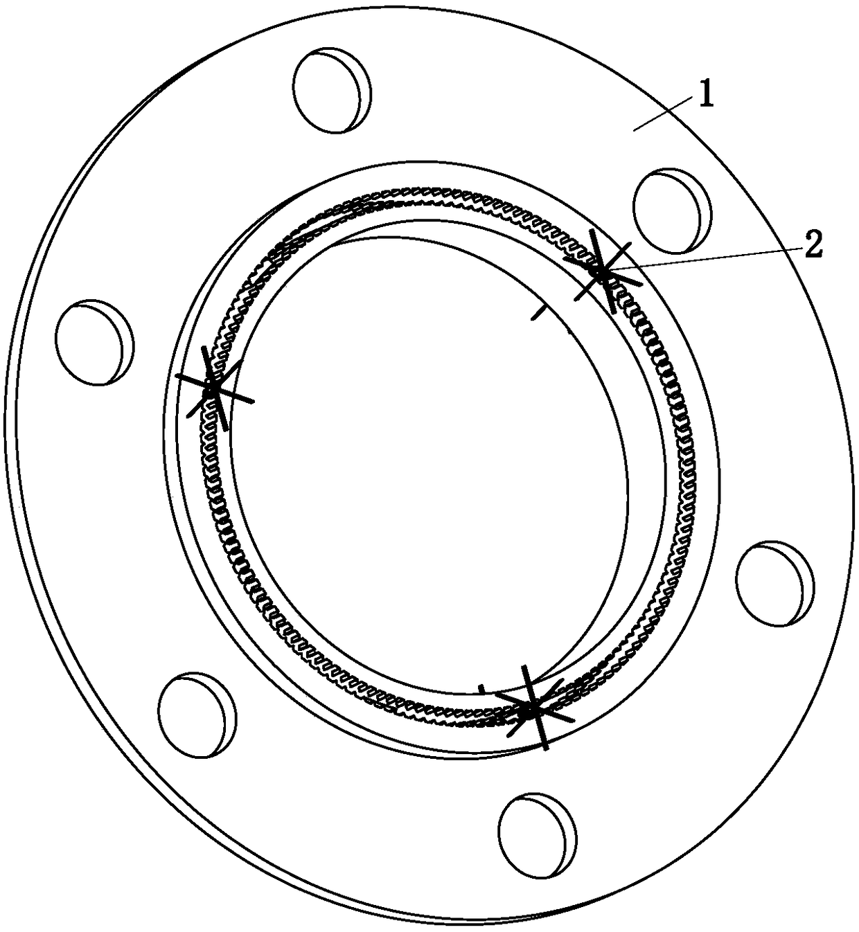
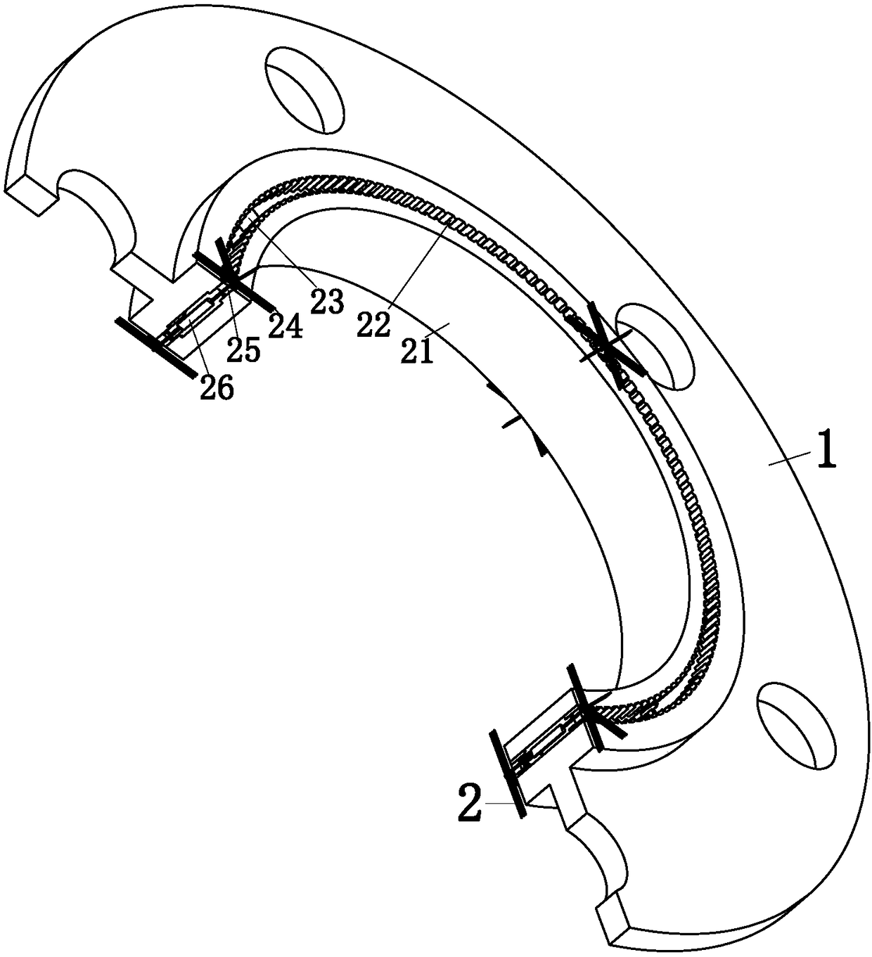
[0011] Such as figure 1 and figure 2 As shown, a self-cleaning oil pipeline connection flange according to the present invention includes a flange mounting seat 1 and a cleaning device 2. The flange mounting seat 1 is provided with bolt holes, and the inside of the flange mounting seat 1 There is a boss, and the flange mounting seat 2 is used for installation to provide an installation position for the present invention, and at the same time, it is used as the connecting body of the oil pipeline; the cleaning device 2 is connected with the flange mounting seat 1, and the cleaning device 2 includes an internal Support ring 21, two ring racks 22, connecting support frame 23, cleaning broom 24, positioning gear 25 and double-head motor 26, the inner su...


PUM


Abstract

The invention relates to the field of petroleum flange manufacturing, and specifically relates to a self-cleaning connection flange for a petroleum pipeline. The self-cleaning connection flange for the petroleum pipeline comprises a flange installation seat and a cleaning device, wherein the cleaning device is connected with the flange installation seat, the cleaning device comprises an inner support ring, two annular racks, a connection support frame, a cleaning besom, a location gear and a double-end motor, and the inner support ring is connected with the flange installation seat through the connection support frame; the two annular racks are installed on the inner support ring and the flange installation seat respectively; the location gear is engaged with the two annular racks; motor main shafts at the two ends of the main shaft of the double-end motor are connected with the location gear respectively; and the cleaning besom is installed at the outer side of the location gear in a manner of interference fit. The underwater connection flange for the petroleum pipeline, which is disclosed by the invention, adopts an annular rack-gear transmission manner to realize periodic cleaning for the junction of the flange of the petroleum pipeline, thus use of the petroleum pipeline is benefited, and the production efficiency is increased.

Description

technical field [0001] The invention relates to the field of oil flange manufacturing, in particular to a self-cleaning oil pipeline connection flange. Background technique [0002] Nowadays, with the continuous development of human civilization, the continuous innovation of industrial level, and the continuous improvement of oil extraction technology, the longest problem encountered in the process of oil extraction is the transmission problem encountered in the process of oil extraction. In the prior art, pipelines are usually used for oil extraction. It can be seen that the requirements for oil transmission pipelines are relatively high in the process of oil extraction, and the selection of connectors for oil transmission pipelines is also important during the transmission process. Pipeline connectors are usually connected by flanges. In the existing oil pipeline connection flanges, it is usually aimed at the connection between two pipelines, and oil pipelines usually form...

Claims


Application Information

Patent Timeline
Patent Type & Authority Patents(China)
IPC IPC(8): F16L23/032B08B1/04
CPCB08B1/002B08B1/04F16L23/032
Inventor 胡来源
Owner 浙江大业法兰有限公司
Why Eureka
Try Eureka