Fire hose coupling connector

A technology for fire hoses and fiber optic connectors, applied in hose connection devices, pipes/pipe joints/fittings, fire rescue, etc., can solve the problems of misjudgment of fire scenes, single function, and inability to accurately grasp the video information of fire scenes, etc., to achieve The effect of small dimensional tolerances

Active Publication Date: 2016-09-21
SHANDONG PACIF OPTICS FIBER & CABLE CO LTD
View PDF5 Cites 3 Cited by
  • Summary
  • Abstract
  • Description
  • Claims
  • Application Information

AI Technical Summary

Problems solved by technology

[0002] The fire hose is a hose used to transport high-pressure water or foam and other flame-retardant liquids. The traditional fire hose is lined with rubber and the outer surface is wrapped with flax braid. The advanced fire hose is made of polymer materials such as polyurethane. In the process of using the fire hose, due to the different distances, it is necessary to use multiple sections of hose for connection. When the distance is far away, the fire hose interface will be used to connect the fire hose. Therefore, the fire hose interface connector It is an indispensable special connection device, but the existing fire hose interface connector has a single function and cannot transmit audio, video and other fire scene information; in the fire fighting work, the command center and firefighters are very blind during the fire fighting process and cannot accurately Mastering the real-time video information of the fire scene may easily cause misjudgment of the fire scene and delay the rescue of firefighting and fire fighting; for this reason, we provide a fire hose interface for audio and video transmission through optical fiber connectors, which has the function of optical information transmission

Method used


Image

  • Fire hose coupling connector
  • Fire hose coupling connector

Examples


Embodiment Construction

[0015] The preferred embodiments of the present invention will be described below in conjunction with the accompanying drawings. It should be understood that the preferred embodiments described here are only used to illustrate and explain the present invention, and are not intended to limit the present invention.

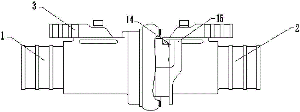
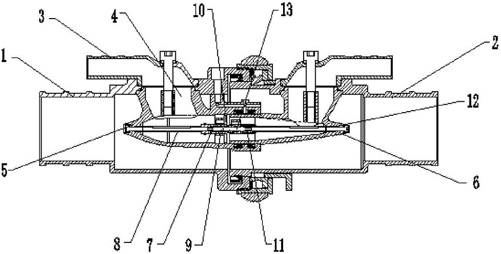
[0016] Such as figure 1 , figure 2 As shown, a fire hose interface optical fiber connector includes a female connector 1 and a male connector 2, and the female connector 1 and the male connector 2 are flexibly connected by a card type, and the female connector 1 and the male connector 2 The top is equipped with an air joint 3, and one end of the air joint 3 is connected to the inner tube 4, and the inner tube 4 is respectively arranged in the inner cavity of the female joint 1 and the male joint 2, and the inner cavity of the female joint 1 and the male joint 2 The cavities are respectively provided with a first inner joint 5 and a second inner joint 6, and both a...


PUM


Abstract

The invention relates to a fire hose coupling connector. The fire hose coupling connector comprises a female joint and a male joint, wherein the female joint is movably connected to the male joint through a thread; air joints are arranged on the tops of the female joint and the male joint, and one ends of the air joints are connected to inner tubes; the inner tubes are arranged in inner cavities of the female joint and the male joint; a first inner connector and a second inner connector are arranged in the inner cavities of the female joint and the male joint, respectively, and are arranged at the bottoms of the inner tubes; the inner cavity of the first inner connector is connected to a first optical fiber rod through a first fixed part; one end of the first optical fiber rod is connected to a first optical fiber magnetic head; an optical fiber inner joint wraps the outer wall of the first optical fiber magnetic head; the inner cavity of the second inner connector is connected to a second optical fiber rod through a second fixed part; and one end of the second optical fiber rod is connected to a second optical fiber magnetic head; and two ceramic inserted cores can be precisely butt-jointed with each other through the optical fiber inner connector, and accurate blind insertion of a fire-fighting connector in actual use can be guaranteed.

Description

technical field [0001] The invention relates to a fiber optic connector for a fire-fighting hose interface, which belongs to the technical field of fire-fighting equipment. Background technique [0002] The fire hose is a hose used to transport high-pressure water or foam and other flame-retardant liquids. The traditional fire hose is lined with rubber and the outer surface is wrapped with flax braid. The advanced fire hose is made of polymer materials such as polyurethane. In the process of using the fire hose, due to the different distances, it is necessary to use multiple sections of hose for connection. When the distance is far away, the fire hose interface will be used to connect the fire hose. Therefore, the fire hose interface connector It is an indispensable special connection device, but the existing fire hose interface connector has a single function and cannot transmit audio, video and other fire scene information; in the fire fighting work, the command center and...

Claims


Application Information

Patent Timeline
Patent Type & Authority Applications(China)
IPC IPC(8): F16L33/00A62C33/00
CPCA62C33/00F16L33/00
Inventor 艾兴余李广省李冠魁赵士云宋来朋郭俊国
Owner SHANDONG PACIF OPTICS FIBER & CABLE CO LTD
Why Eureka
Try Eureka