
Speed ​​control method and device for PTZ camera

A speed control device and speed control technology, applied in the field of camera transmission, can solve the problems of unsuitable pan-tilt camera application scenarios and high hardware requirements, and achieve the effect of eliminating the shaking phenomenon

Active Publication Date: 2018-09-18
成都全景智能科技有限公司
View PDF5 Cites 2 Cited by
  • Summary
  • Abstract
  • Description
  • Claims
  • Application Information

AI Technical Summary

Problems solved by technology

However, these anti-shake technologies have too high requirements on hardware, and are mainly applicable to the hand-shake problem during the shooting process of mobile phones and cameras, and are not suitable for application scenarios where the pan-tilt camera is operated by a motor

Method used

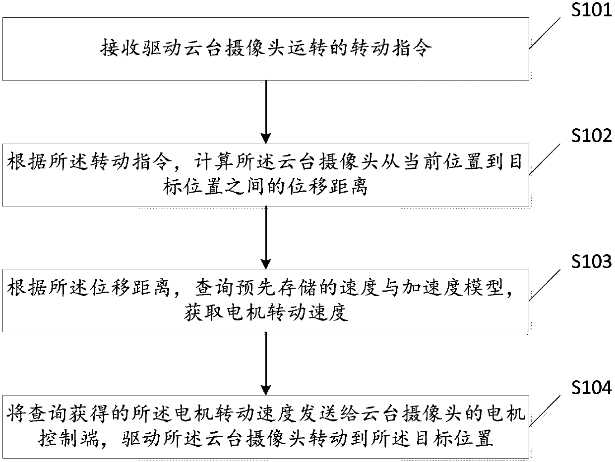
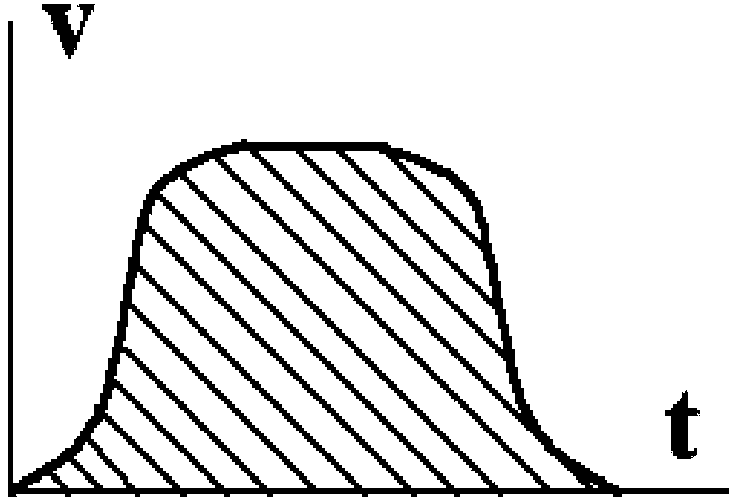
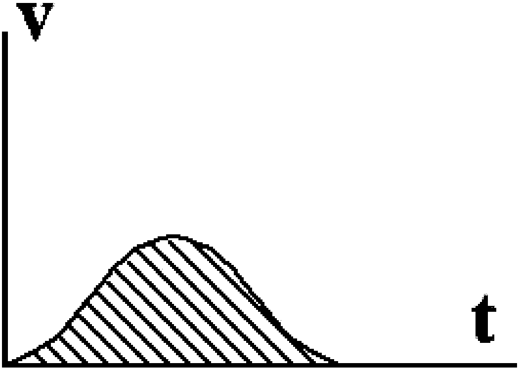

Image

  • Speed ​​control method and device for PTZ camera
  • Speed ​​control method and device for PTZ camera
  • Speed ​​control method and device for PTZ camera

Examples


Embodiment Construction

[0064] In order to enable those skilled in the art to better understand the solutions of the present invention, the technical solutions in the embodiments of the present invention will be clearly and completely described below in conjunction with the drawings in the embodiments of the present invention.

[0065] In some processes described in the specification and claims of the present invention and the above-mentioned drawings, a plurality of operations appearing in a specific order are contained, but it should be clearly understood that these operations may not be performed in the order in which they appear herein Execution or parallel execution, the serial numbers of the operations, such as 101, 102, etc., are only used to distinguish different operations, and the serial numbers themselves do not represent any execution order. Additionally, these processes can include more or fewer operations, and these operations can be performed sequentially or in parallel. It should be n...


PUM


Abstract

The invention discloses a speed control device for a holder camera. The device comprises an instruction reception unit used for receiving a rotation instruction for driving the holder camera to rotate, a displacement calculation unit used for calculating a displacement distance of the holder camera from the present position to a target position according to the rotation instruction, a speed querying unit used for querying a pre-stored speed and an acceleration model according to the displacement distance to acquire a motor rotation speed, and a driving control unit used for sending the motor rotation speed acquired through querying to a motor control end of the holder camera to drive the holder camera to rotate to the target position. Through the device, jittering of the holder camera can be eliminated to a great degree at relatively low cost.

Description

technical field [0001] The present invention relates to camera transmission technology, and more particularly, to a speed control method and device for a pan-tilt camera. Background technique [0002] The pan-tilt camera is provided with a rotating motor. When the motor drives the camera to rotate, it needs the camera to rotate to a predetermined position within a predetermined time, so the camera needs to rotate to a predetermined position at the highest speed. In the prior art, the motor directly drives the camera to rotate at a rated maximum speed, so the picture captured by the camera will shake, thereby affecting the shooting quality. [0003] The existing anti-shake technology mainly includes natural anti-shake technology, such as: increasing the sensitivity to increase the shutter speed; optical anti-shake technology, such as: using a special lens or the structure of a charge coupled device (CCD), which can Use these anti-shake technologies to reduce the impact cause...

Claims


Application Information

Patent Timeline
Patent Type & Authority Patents(China)
IPC IPC(8): G05D13/52
CPCG05D13/52
Inventor 熊道云
Owner 成都全景智能科技有限公司
Learn More