
Parallel mechanism based single drive one-translation two-rotation three-dimensional sand filling vibration-compaction machine

A single-drive, parallel-connected technology, used in the manufacture of fluids and fuses using vibration, can solve the problems of single vibration mode and difficulty in improving sand filling density, and achieve a high-quality sand filling density, simple structure, and convenient manufacturing and maintenance. Effect

Active Publication Date: 2016-09-21
SHANGHAI UNIV OF ENG SCI
View PDF5 Cites 7 Cited by
  • Summary
  • Abstract
  • Description
  • Claims
  • Application Information

AI Technical Summary

Problems solved by technology

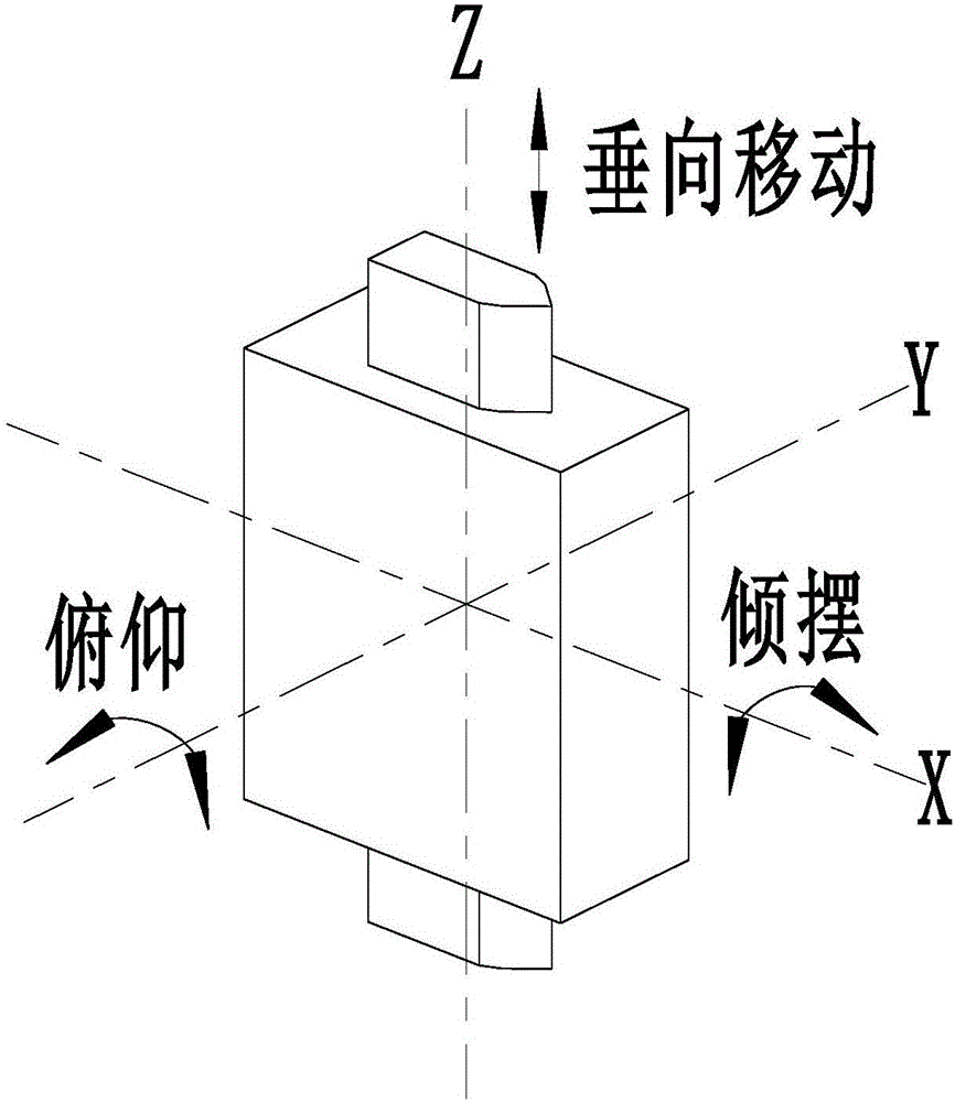
[0004] The technical problem to be solved by the present invention is to provide a single-drive-translation-two-rotation three-dimensional sand filling vibrator based on a parallel mechanism. Three-dimensional vibration can better overcome the shortcomings of the existing fuse sand filling vibrator, which has a single vibration mode and the sand filling density is difficult to improve, and further improve the fuse production efficiency and product qualification rate

Method used

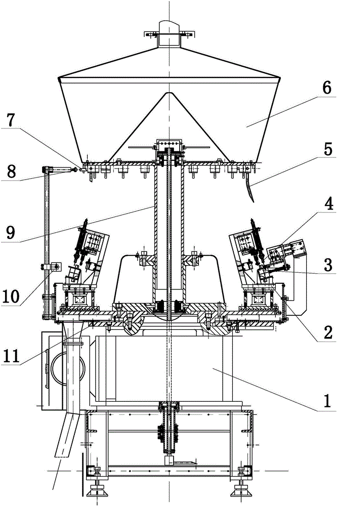

Image

  • Parallel mechanism based single drive one-translation two-rotation three-dimensional sand filling vibration-compaction machine
  • Parallel mechanism based single drive one-translation two-rotation three-dimensional sand filling vibration-compaction machine
  • Parallel mechanism based single drive one-translation two-rotation three-dimensional sand filling vibration-compaction machine

Examples


Embodiment 1

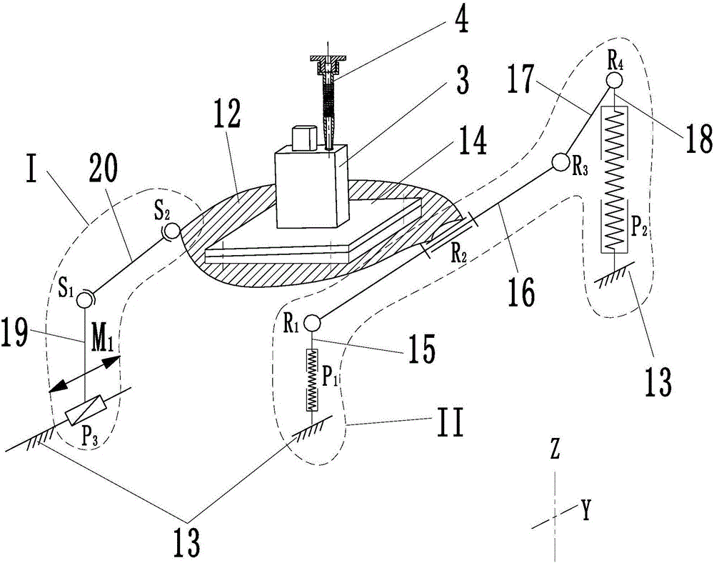
[0046] The active branch chain I includes the third moving pair P3, the first connecting rod 19 and the second connecting rod 20:

[0047] The lower end of the first connecting rod 19 is connected to the fixed base 13 through the third moving pair P3, and the first connecting rod 19 can translate along the Y direction on the fixed base 13;

[0048] The front end of the second connecting rod 20 is spherically hinged on the upper end of the first connecting rod 19, and the rear end is spherically hinged on the left side of the moving platform 12;

[0049] The passive branch chain II includes the first spring damper P1, the first driven rod 15, the second driven rod 16, the third driven rod 17, the fourth driven rod 18 and the second spring damper P2:

[0050] One end of the first spring damper P1 is installed on the fixed base 13, and the other end is connected with the first driven rod 15, the first spring damper P1 can elastically expand and contract along the Z direction, the...

Embodiment 2

[0061] The active branch chain I includes the third mobile pair P3, the first connecting rod 19 and the second connecting rod 20:

[0062] The lower end of the first connecting rod 19 is connected to the fixed base 13 through the third moving pair P3, and the first connecting rod 19 can translate along the Y direction on the fixed base 13;

[0063] The front end of the second connecting rod 20 is spherically hinged on the upper end of the first connecting rod 19, and the rear end is spherically hinged on the left side of the moving platform 12;

[0064] The passive branch chain II includes the first spring damper P1, the first driven rod 15, the second driven rod 16 and the fourth spring damper P4:

[0065] The lower end of the first driven rod 15 is installed on the fixed base 13 through the first spring damper P1, and the first spring damper P1 can elastically expand and contract along the Z direction, thereby driving the first driven rod 15 to translate along the Z directio...

Embodiment 3

[0077] Active branch chain 1 comprises first connecting rod 19 and second connecting rod 20:

[0078] The lower end of the first connecting rod 19 is rotatably connected to the fixed base 13, where the rotation axis of the revolving pair R7 is along the X direction;

[0079] The front end of the second connecting rod 20 is spherically hinged on the upper end of the first connecting rod 19, and the rear end is spherically hinged on the left side of the moving platform 12;

[0080] The passive branch chain II includes the first driven rod 15, the second driven rod 16, the fourth spring damper P4, the fifth rotating pair R5 containing the torsion spring 25 and the sixth rotating pair R6 containing the torsion spring 25:

[0081] The lower end of the first driven rod 15 is rotatably mounted on the fixed base 13, and constrained by the torsion spring 25, the first driven rod 15 can rotate around the lower end;

[0082] The front end of the second driven rod 16 is rotatably mounted...


PUM


Abstract

The invention discloses a parallel mechanism based single drive one-translation two-rotation three-dimensional sand filling vibration-compaction machine. The machine comprises a fixed pedestal, a movable platform, a driving branch chain I and a driven branch chain II; the driving branch chain I and the driven branch chain II are respectively positioned at the left and right sides of the fixed pedestal; the two ends of the driving branch chain I are respectively connected to the fixed pedestal and the movable platform; the two ends of the driven branch chain II both are connected to the fixed pedestal; and the driven branch chain II is connected to the movable platform via a rotation pair R2. When a single drive is applied to the driving branch chain I, the movable platform can simultaneously carry out a three-dimensional vibration form of vertical vibration, deflection vibration and pitch vibration; the vibration-compaction machine has the characteristics of single input and multiple outputs, and is simple in structure, convenient in manufacturing and maintenance, energy-saving and reliable; through regulating a displacement drive on a moving pair, the vibration frequency and amplitude of the vibration platform can be changed; and by combining with a sand filling process, the fuse sand filling compactness is improved, and the fuse production efficiency is improved.

Description

technical field [0001] The invention relates to the field of mechanical vibration, in particular to a sand filling vibrator with a fuse single-drive multi-dimensional vibration output. Background technique [0002] The fuse is a circuit protector with high segmentation capability. The fuse tube is filled with quartz sand as the arc extinguishing medium. When the short-circuit current passes, the arc is extinguished by the quartz sand and absorbs the arc energy. It has a strong arc extinguishing ability. , can greatly improve the electrical stability and thermal stability of the protected electrical equipment. The chemical composition, shape, particle size and other characteristics of quartz sand all have an impact on the arc extinguishing performance of the fuse. Studies have shown that the tightness of the quartz sand filling in the fuse package directly affects the segmentation ability of the fuse. The increase of the fuse can improve a series of action performance when t...

Claims


Application Information

Patent Timeline
Patent Type & Authority Applications(China)
IPC IPC(8): H01H69/02B06B1/10
CPCB06B1/10H01H69/02
Inventor 杭鲁滨秦伟皇甫亚波程武山张敏良
Owner SHANGHAI UNIV OF ENG SCI
Learn More