Built-in permanent magnet motor and rotor thereof

A technology for permanent magnet motors and rotors, which is applied in the direction of magnetic circuit rotating parts, magnetic circuit shape/style/structure, etc., and can solve problems such as high magnetic leakage coefficient and poor magnetic isolation effect

Inactive Publication Date: 2016-09-21
CSR ZHUZHOU ELECTRIC LOCOMOTIVE RES INST
View PDF2 Cites 0 Cited by
  • Summary
  • Abstract
  • Description
  • Claims
  • Application Information

AI Technical Summary

Problems solved by technology

However, the current built-in tangential permanent magnet motor has a poor magnetic isolation effect, which makes the magnetic flux leakage coefficient higher

Method used


Image

  • Built-in permanent magnet motor and rotor thereof

Examples


Embodiment Construction

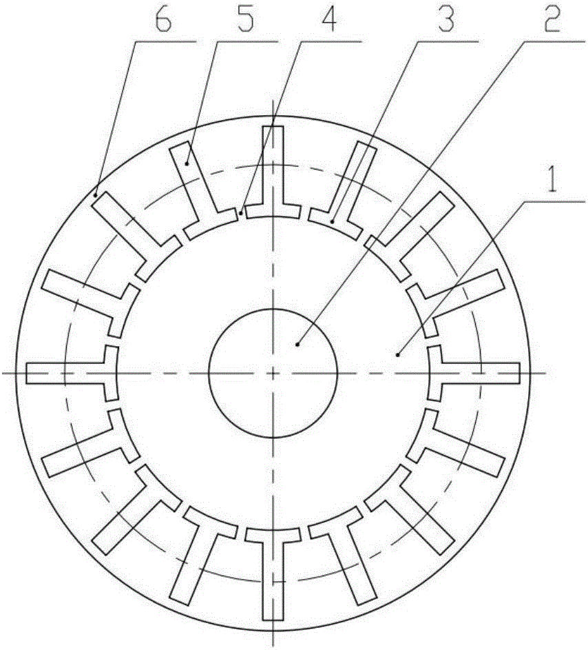
[0025] The core of the present invention is to provide a rotor of a built-in permanent magnet motor to reduce the flux leakage coefficient of the built-in permanent magnet motor. Another core of the present invention is to provide an interior permanent magnet motor with the above-mentioned rotor.

[0026] The following will clearly and completely describe the technical solutions in the embodiments of the present invention with reference to the accompanying drawings in the embodiments of the present invention. Obviously, the described embodiments are only some, not all, embodiments of the present invention. Based on the embodiments of the present invention, all other embodiments obtained by persons of ordinary skill in the art without making creative efforts belong to the protection scope of the present invention.

[0027] Such as figure 1 As shown, the present invention discloses a rotor of a built-in permanent magnet motor, including a rotating shaft 2, a rotor punch 1, a pe...


PUM


Abstract

The invention discloses a rotor of a built-in permanent magnet motor. The rotor comprises a rotating shaft, a rotor punching plate, permanent magnets and slot wedges, wherein the rotor punching plate is sleeved on the rotating shaft, and permanent magnet slots and slot wedge slots are formed in the outer side of the rotor punching plate; the slot wedge slots are positioned between the permanent magnet slots and the rotating shaft; the permanent magnets are arranged in the permanent magnet slots; the slot wedges are arranged in the slot wedge slots; first magnetic isolation bridges are arranged between the permanent magnet slots and the outer side of the rotor punching plate; and second magnetic isolation bridges are arranged between the adjacent slot wedge slots. According to the rotor, the first magnetic isolation bridges are arranged between the permanent magnet slots and the outer side of the rotor punching plate, the permanent magnet slots are through holes formed in the rotor punching plate, and the second magnetic isolation bridges are arranged between the adjacent slot wedge slots; through the arrangement, the width of each magnetic bridge can be adjusted, so that the magnetic density of air gaps is high, and the utilization rate of the permanent magnets is high, namely the magnetic leakage factor of the built-in permanent magnet motor is reduced. The invention also discloses the built-in permanent magnet motor with the rotor.

Description

technical field [0001] The invention relates to the technical field of permanent magnet motors, in particular to a built-in permanent magnet motor and its rotor. Background technique [0002] With the advancement of technology and economic development, the requirements of high efficiency, energy saving and emission reduction have become the basic principles of various industries. Permanent magnet motors with high efficiency and low energy consumption are currently an effective way to achieve this goal, and are currently widely used in industry, agriculture, construction and transportation. [0003] In permanent magnet motors, commonly used rotor magnetic circuit structures include surface rotor magnetic circuit structure and built-in rotor magnetic circuit structure. Among them, the surface rotor magnetic circuit structure can maximize the air gap magnetic density, but the permanent magnet has the risk of demagnetization, while the built-in magnetic circuit structure has si...

Claims


Application Information

Patent Timeline
Patent Type & Authority Applications(China)
IPC IPC(8): H02K1/22H02K1/28
CPCH02K1/22H02K1/28
Inventor 冯江华李坤刘春秀彭俊何思源王健陈致初罗英露刘雄史俊旭邹杰
Owner CSR ZHUZHOU ELECTRIC LOCOMOTIVE RES INST
Why Eureka
Try Eureka