Motor permanent magnet fixing structure, fixing method and motor including the same

A technology of fixing structure and fixing method, which is applied in the direction of magnetic circuit shape/style/structure, magnetic circuit rotating parts, manufacturing stator/rotor body, etc. It can solve the problems of weak protection at both ends of permanent magnets, insufficient protection of permanent magnets The adverse effects of motor efficiency and other issues can be achieved to reduce the overall thickness, reduce the gap, and reduce the waiting time.

Active Publication Date: 2016-08-03
GREE ELECTRIC APPLIANCES INC
View PDF6 Cites 0 Cited by
  • Summary
  • Abstract
  • Description
  • Claims
  • Application Information

AI Technical Summary

Problems solved by technology

The method of binding the permanent magnet with carbon fiber is relatively weak for the protection of the two ends of the permanent magnet, and the accident of the permanent magnet being thrown out is prone to occur.
The method of installing a protective cover to protect the permanent magnet cannot avoid the defect that the gap between the protective cover and the permanent magnet is too large, and the protection of the permanent magnet is not reliable enough, and the large gap will increase the magnetic flux leakage coefficient, which has an adverse effect on the efficiency of the motor.

Method used


Image

  • Motor permanent magnet fixing structure, fixing method and motor including the same
  • Motor permanent magnet fixing structure, fixing method and motor including the same

Examples


Embodiment Construction

[0022] The present invention will be described in detail below with reference to the accompanying drawings and examples. It should be noted that, in the case of no conflict, the embodiments in the present application and the features in the embodiments can be combined with each other.

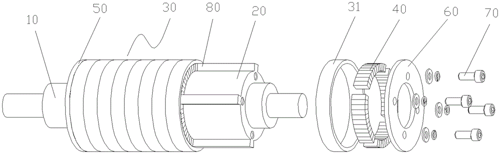
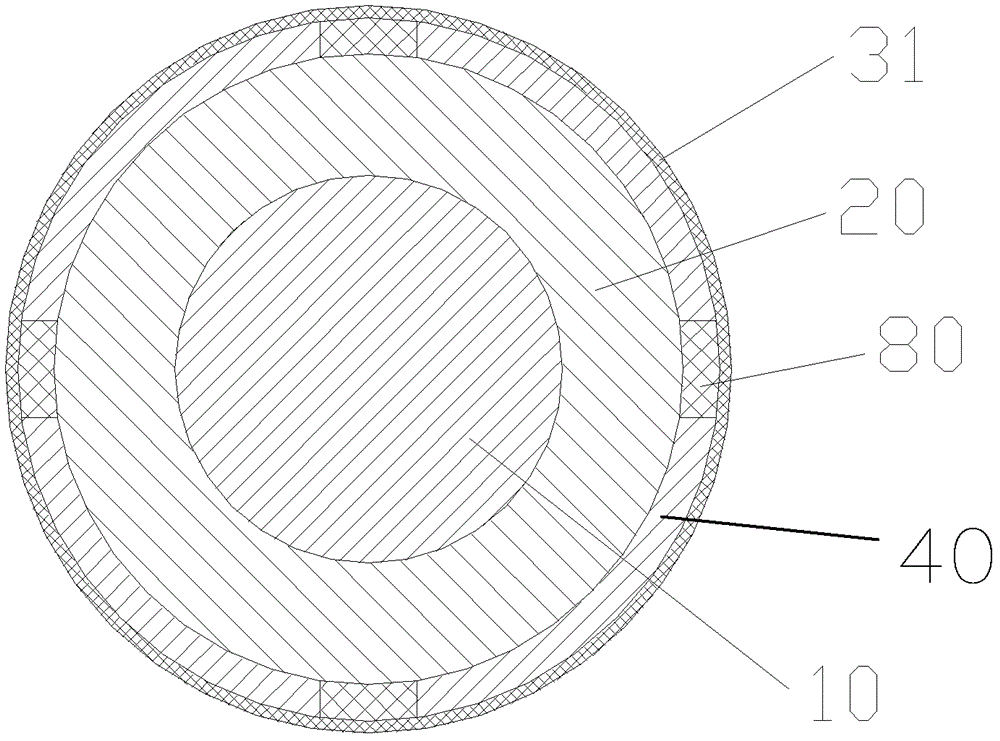
[0023] Such as Figure 1~2 As shown, according to the embodiment of the present invention, the motor permanent magnet fixing structure includes a rotor core 20 , a composite material collar 31 , a permanent magnet 40 , fastening steel plates 50 , fastening steel plates 60 and aluminum strips 80 .

[0024] Wherein, the rotor core 20 made of silicon steel sheets is sleeved on the outer surface of the motor shaft 10 and rotates together with the motor shaft 10 . The composite collar 31 made of carbon fiber reinforced composite material is sleeved on the outer surface of the rotor core 20, wherein the carbon fiber reinforced composite material may be carbon fiber reinforced 6376 modified epoxy res...


PUM


Abstract

The invention provides a fixed structure and a fixing method of motor permanent magnets and a motor comprising the fixed structure. The fixed structure of the motor permanent magnets comprises a rotor iron core, a composite material sleeve and the permanent magnets, wherein the composite material sleeve is sleeved on the outer surface of the rotor iron core and comprises a plurality of composite material sleeve rings which are arranged along the axial direction and independent from one another; each permanent magnet is arranged between a gap between the rotor iron core and each composite material sleeve ring. The fixing method comprises the following steps: coating anaerobic adhesive on the outer surface of the rotor iron core and the inner surfaces of the composite material sleeve rings, and sleeving the composite material sleeve rings on the rotor iron core; embedding the permanent magnets in the gaps between the rotor iron core and the composite material sleeve rings; and repeating the steps until the permanent magnets are all distributed on the outer surface of the rotor iron core, wherein the composite material sleeve rings form the composite material sleeve along the axial direction. According to the fixed structure and the fixing method of the motor permanent magnets and the motor comprising the fixed structure, the assembling efficiency and assembling precision of the permanent magnets can be improved, and the gaps between the permanent magnets and a stator winding are reduced so that the leakage coefficient is reduced.

Description

technical field [0001] The invention relates to the field of motors, in particular to a motor permanent magnet fixing structure, a fixing method and a motor including the structure. Background technique [0002] At present, high-speed motors are widely used in the field of commercial air conditioners. However, due to the poor reliability of the rotor permanent magnets and the low tensile strength of the permanent magnets, the centrifugal force on the permanent magnets must be limited within a certain range, and the motor speed cannot be exceeded. High, the outer diameter of the rotor can not be too large. This has caused the existing high-speed motors to be difficult to meet the increasingly higher motor speed requirements of commercial air conditioners. In order to overcome this difficulty, it is necessary to take effective protection measures for the permanent magnets to increase the firmness of the permanent magnets. [0003] There are two existing measures to protect t...

Claims


Application Information

Patent Timeline
Patent Type & Authority Patents(China)
IPC IPC(8): H02K1/28H02K15/03
Inventor 夏光辉刘华张治平钟瑞兴蒋楠蒋彩云谢蓉傅鹏闫秀兵
Owner GREE ELECTRIC APPLIANCES INC
Why Eureka
Try Eureka