Auxiliary cabinet mounting rack

A technology for installing racks and cabinets, applied in the direction of rack/frame structure, etc., can solve problems such as major safety hazards, aging and deformation of installation cabinets

Inactive Publication Date: 2016-09-21
STATE GRID SHANDONG ELECTRIC POWER +1
View PDF3 Cites 2 Cited by
  • Summary
  • Abstract
  • Description
  • Claims
  • Application Information

AI Technical Summary

Problems solved by technology

Therefore, it is required that the installation cabinets in the main control room of the substation must strictly comply with the standard cabinet specifications; however, many installation cabinets in the substation are old in style and the installation position of the equipment in the cabinet is not planned for the installation position of the data network equipment, which does not meet the on-site installation requirements of the dispatching data network equipment. , such as the deformation of the vertical installation column in the installation cabinet, the installation location without reasonable planning, etc.
The staff of the dispatching data network are engaged in on-site installation and commissioning. Due to problems such as on-site installation location, inconsistent equipment width, and aging of installation cabinets, the on-site installation and commissioning work takes a long time, and there are large safety hazards

Method used


Image

  • Auxiliary cabinet mounting rack
  • Auxiliary cabinet mounting rack
  • Auxiliary cabinet mounting rack

Examples


Embodiment Construction

[0019] The present invention will be described in detail below in conjunction with the accompanying drawings.

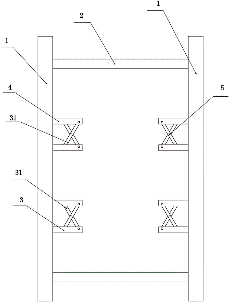
[0020] like figure 1 As shown, the side bars 1 are two oppositely arranged, and the bars on both sides are fixedly connected together by connecting bars, and the bars on both sides and the connecting bars constitute the frame. There are two pairs of support assemblies arranged up and down between the two side bars, one of the paired two support assemblies is fixed on the left side bar, and the other of the paired two support assemblies is fixed on the right side on the sidebar.

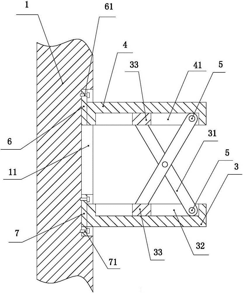
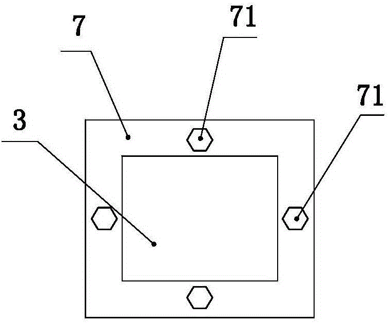
[0021] like figure 2 As shown, an adjustment hole 11 is provided on the side of the side bar, and the adjustment hole is a vertical elongated hole, and a lower strut 3 is provided below the adjustment hole, and the lower strut is a square metal rod, such as image 3 As shown, a fixed plate 7 is fixed on the installation end of the lower brace, the fixed plate is a square metal plate, and...


PUM


Abstract

The invention relates to an auxiliary cabinet mounting rack and is convenient for mounting the scheduling data network onsite equipment. The rack comprises side rods, connection rods and supporting assemblies, wherein the two pairs of supporting assemblies are arranged between the two side rods, the supporting assemblies are respectively arranged on the corresponding side rods in pairs, the supporting assemblies mainly comprise lower supporting rods, upper supporting rods and swinging rods, mounting ends of the lower supporting rods are fixed on the side rods, upper portions of the lower supporting rods are provided with the upper supporting rods, mounting ends of the upper supporting rods are in sliding connection with the side rods, latching bolts are arranged between the mounting ends of the upper supporting rods and the side rods, the two swinging rods which are in hinge connection to form an X structure are arranged between the upper supporting rods and the lower supporting rods, an upper end of the first swinging rod is in hinge connection with the upper supporting rods, a lower end of the first swinging rod is sliding connection with the lower supporting rods, an upper end of the second swinging rod is in sliding connection with the upper supporting rods, and a lower end of the second swinging rod is in hinge connection with the lower supporting rods. Through the rack, mounting of switches in different dimensions and a router can be conveniently realized.

Description

technical field [0001] The invention relates to the technical field of dispatching, in particular to a cabinet auxiliary installation frame used for dispatching data networks. Background technique [0002] The dispatching data network is an important part of the power grid dispatching automation system, and the field equipment of the dispatching data network is divided into routers and switches. Therefore, it is required that the installation cabinets in the main control room of the substation must strictly comply with the standard cabinet specifications; however, many installation cabinets in the substation are old in style and the installation position of the equipment in the cabinet is not planned for the installation position of the data network equipment, which does not meet the on-site installation requirements of the dispatching data network equipment. , Such as the deformation of the vertical installation column in the installation cabinet, the installation location ...

Claims


Application Information

Patent Timeline
Patent Type & Authority Applications(China)
IPC IPC(8): H05K7/18
CPCH05K7/18
Inventor 董晨晖林祺蓉王俏俏管荑王晓军施雨刘红霞林琳
Owner STATE GRID SHANDONG ELECTRIC POWER
Why Eureka
Try Eureka