Shifting device for transmission

A shifting device and transmission technology, which is applied to transmission parts, transmission control, components with teeth, etc., and can solve the problem that the shifting mechanism occupies the shifting state, etc.

Active Publication Date: 2018-02-06
SCHAEFFLER TECH AG & CO KG
View PDF7 Cites 0 Cited by
  • Summary
  • Abstract
  • Description
  • Claims
  • Application Information

AI Technical Summary

Problems solved by technology

[0003] When transporting and installing such a shifting mechanism, the problem arises that the shifting mechanism can assume undefined shifting states without being coupled to other transmission components

Method used


Image

  • Shifting device for transmission
  • Shifting device for transmission
  • Shifting device for transmission

Examples


Embodiment Construction

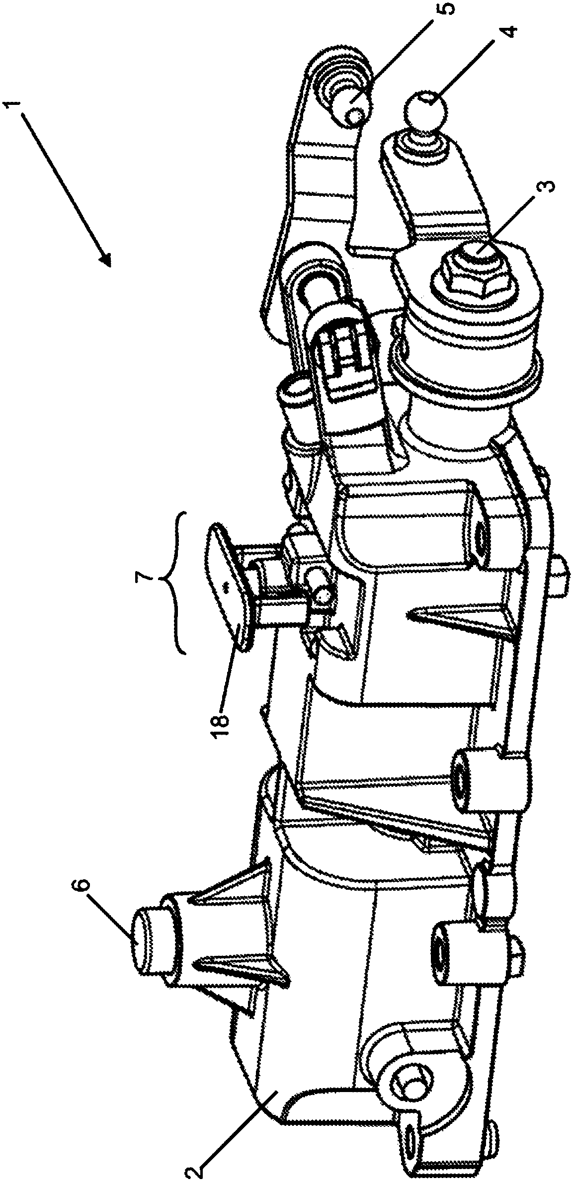
[0028] figure 1 A three-dimensional schematic view of a shifting device 1 as an embodiment of the present invention is shown, which is formed as a shifting mechanism housing. The shifting device 1 is used to convert, via a transmission, in particular a form-fitting transmission, or via a cable drive, a shifting and / or selection movement by an actuating device or by a driver into a shifting movement of a transmission or a gear box. gear and / or select a sport. The shifting device 1 is designed for integration and / or installation in a vehicle.

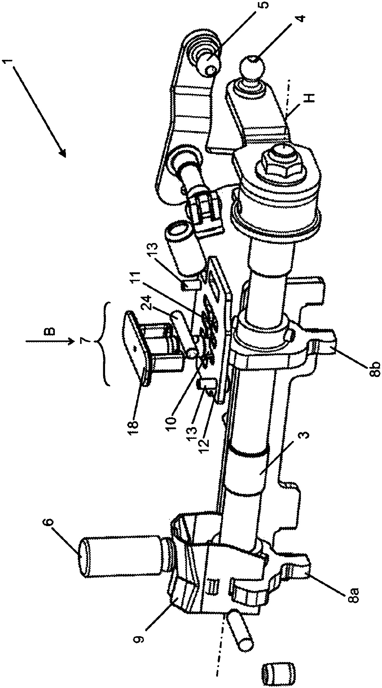
[0029] The shifting device 1 comprises a housing section 2 , which is designed as a cover, wherein the housing section 2 can be slipped onto a connecting housing (not shown) and connected thereto, so that an interior, in particular a shifting, is formed. space. The shifting shaft 3 is mounted in the housing section 2 , said shifting shaft figure 1 can only be seen at the protruding ends in the figure 2 shown in full. The selector s...


PUM


Abstract

In vehicles, shifting and / or selecting movements for shifting or selecting a gear are implemented on the transmission side by way of shifting mechanisms. In the case of transporting and assembling of shifting mechanisms of this type, the problem occurs that, without being coupled to further transmission parts, the shifting mechanisms can assume a non-defined shifting state. To this end, a shifting arrangement (1) for a transmission is configured with a housing section (2) for delimiting a shifting chamber, with a shift shaft (3), wherein the shift shaft (3) is arranged movably in the shifting chamber, with a shift guide plate device (12), wherein the shift guide plate device (12) is connected fixedly to the housing section (2), with a securing device (7), wherein the securing device (7) comprises a securing section (17), wherein the securing section (17) can be moved between a securing position and a release position, wherein, in the securing position of the securing section (17), the shift shaft (3) is coupled to the housing section (2) via the securing section (17), and wherein, in the release state of the securing section (17), the shift shaft (3) is released, wherein, in the securing position, the securing section (17) is arranged so as to overlap with respect to the shift guide plate device (12) in a radial direction with respect to the shift shaft (3).

Description

technical field [0001] The invention relates to a shifting device for a transmission. Background technique [0002] In a vehicle, a shifting and / or selection movement is effected on the transmission side by means of a shifting mechanism to switch or select a gear. A typical shifting mechanism includes a shifting shaft, which is moved in the longitudinal direction for selecting a gear or a shift channel and pivots about its own longitudinal axis for shifting gears. As a rule, selector shafts have other functional areas besides the selector lever for actuating the selector shaft, such as locking areas for controlling the selection or shifting forces and positively guided areas in order to enable only the movement of the selector shaft , said movement is necessary for a gear shift and / or selection movement. [0003] When transporting and installing such a shifting mechanism, the problem arises that the shifting mechanism can assume undefined shifting states without being coup...

Claims


Application Information

Patent Timeline
Patent Type & Authority Patents(China)
IPC IPC(8): F16H63/34
CPCF16H63/34F16H63/20F16H2057/0056F16H2061/242F16H2061/245F16H2063/005F16H2063/208F16H2063/3076F16H2063/3083
Inventor 约亨·勒费尔曼马库斯·罗斯特
Owner SCHAEFFLER TECH AG & CO KG
Why Eureka
Try Eureka