Underground ventilation pipeline
A technology of pipes and ventilation holes, which is applied in the direction of air quality improvement, electrical program control, and analysis of gas mixtures. It can solve problems such as poor growth, airtightness and water permeability, and low survival rate of newly planted green plants, so as to improve breathing conditions. , the effect of saving energy
- Summary
- Abstract
- Description
- Claims
- Application Information
AI Technical Summary
Problems solved by technology
Method used
Image
Examples
no. 1 example
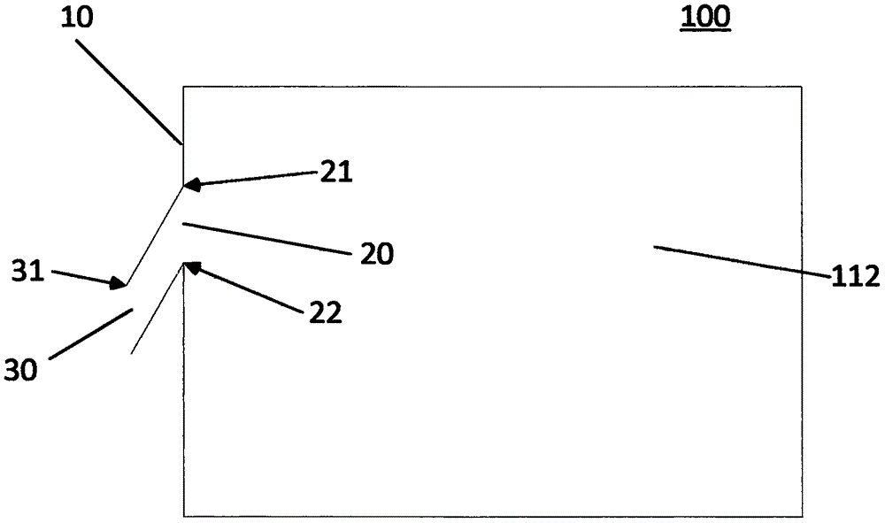
[0022] see figure 1 , the underground ventilation pipe 100 is placed flatly in the soil below the plants, and the side wall 10 of the underground ventilation pipe 100 is provided with a ventilation hole 20, and the edge of the ventilation hole 20 extends outwards and downwards to form an outer hole 30, the outer hole 30 The highest point of the upper edge 31 is lower than the lowest point of the lower edge 22 of the vent hole 20 .
[0023] In this embodiment, the vent hole 20 is a round hole, and in other embodiments, the vent hole 20 may also be a square hole or any irregular hole.
[0024] In the present embodiment, only one vent hole 20 is provided. In most cases, the side wall 10 of an underground vent pipe 100 is provided with a plurality of vent holes 20. In some embodiments, the plurality of vent holes can also be connected horizontally. Together they become a ribbon vent.
[0025] The end of the underground ventilating pipe 100 is either closed, or directly connected...
no. 2 example
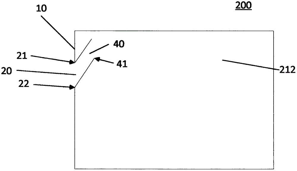
[0029] see figure 2 , the underground ventilation pipe 200 is placed flatly in the soil below the plants, and the side wall 10 of the underground ventilation pipe 200 is provided with a ventilation hole 20, and the edge of the ventilation hole 20 extends inwards and upwards to form an inner hole 40. The highest point of the upper edge 21 is lower than the lowest point of the lower edge 41 of the inner hole 40 .
[0030] In this embodiment, the vent hole 20 is a round hole, and in other embodiments, the vent hole 20 may also be a square hole or any irregular hole.
[0031] In the present embodiment, only one vent hole 20 is provided. In most cases, the side wall 10 of an underground vent pipe 200 is provided with a plurality of vent holes 20. In some embodiments, the plurality of vent holes can also be connected horizontally. Together they become a ribbon vent.
[0032] The end of the underground ventilation pipe 200 is either closed, or directly connected to the ground, or ...
no. 3 example
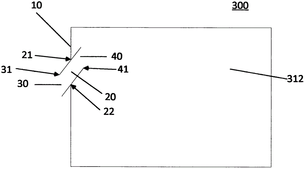
[0036] see figure 2 , the underground ventilation pipe 300 is placed flatly in the soil below the plants, and the side wall 10 of the underground ventilation pipe 300 is provided with a ventilation hole 20, and the edge of the ventilation hole 20 extends outwards and downwards to form an outer hole 30, while the ventilation hole 20 The edge of the outer hole 30 extends inwardly and upwardly to form an inner hole 40 , and the highest point of the upper edge 31 of the outer hole 30 is lower than the lowest point of the lower edge 41 of the inner hole 40 .
[0037] In this embodiment, the vent hole 20 is a round hole, and in other embodiments, the vent hole 20 may also be a square hole or any irregular hole.
[0038] In the present embodiment, only one vent hole 20 is provided. In most cases, the side wall 10 of an underground vent pipe 300 is provided with a plurality of vent holes 20. In some embodiments, the plurality of vent holes can also be connected horizontally. Togethe...
PUM
 Abstract
Description
Claims
Application Information
 - R&D
- Intellectual Property
- Life Sciences
- Materials
- Tech Scout
- Unparalleled Data Quality
- Higher Quality Content
- 60% Fewer Hallucinations
Browse by: Latest US Patents, China's latest patents, Technical Efficacy Thesaurus, Application Domain, Technology Topic, Popular Technical Reports.
© 2025 PatSnap. All rights reserved.Legal|Privacy policy|Modern Slavery Act Transparency Statement|Sitemap|About US| Contact US: help@patsnap.com


