
A medical cervical spine massage robot

A robot and cervical spine technology, applied in the field of medical equipment, can solve the problems of low work efficiency, high equipment vibration, uneven massage force, etc., and achieve the effect of increasing work efficiency, improving recovery speed, and increasing massage effect

Inactive Publication Date: 2017-12-19
XIAN HONGHUI HOSPITAL
View PDF4 Cites 0 Cited by
  • Summary
  • Abstract
  • Description
  • Claims
  • Application Information

AI Technical Summary

Problems solved by technology

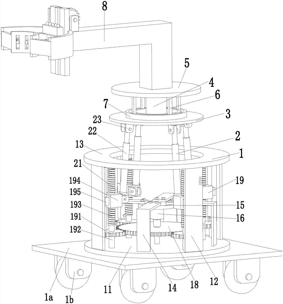
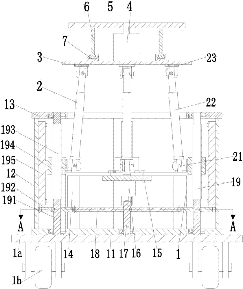
[0005] In order to solve the above problems, the present invention provides a medical cervical spine massage robot, which can solve the problems of poor massage effect, uneven massage force, high labor intensity, complicated operation, low work efficiency and limited range of massage in manual massage or massage pillow massage. It can also solve the problems of poor massage effect, difficult to control the massage force, unadjustable massage height, single massage method, high equipment vibration, poor stability and small application range in existing automatic massage equipment. The function of automatic massage not only has the comfort level of manual massage, but also has the advantages of simple operation, good massage effect, uniform massage force, adjustable massage force, adjustable massage height, large massage range, wide application range and high work efficiency. Provides a new way to automate cervical spine massage

Method used


Image

  • A medical cervical spine massage robot
  • A medical cervical spine massage robot
  • A medical cervical spine massage robot

Examples


Embodiment Construction

[0025] In order to make the technical means, creative features, goals and effects achieved by the present invention easy to understand, the present invention will be further described below in conjunction with specific illustrations.

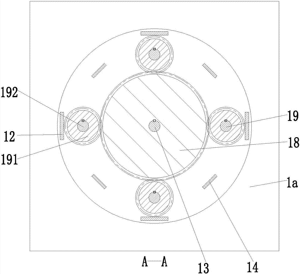
[0026] Such as Figure 1 to Figure 5 As shown, a medical cervical spine massage robot includes a fixed frame 1, a base plate 1a is installed on the lower end surface of the fixed frame 1, and four universal wheels 1b are symmetrically installed on the lower end surface of the base plate 1a, passing through the lower end surface of the base plate 1a. The four universal wheels 1b can move the present invention to a designated position at will, and the operation is simple and convenient; the fixed frame 1 includes a fixed platform 11 installed on the upper end surface of the bottom plate 1a, and the upper end surface of the fixed platform 11 is welded symmetrically with four Supporting panel 12, the upper ends of four supporting panels 12 are welde...


PUM


Abstract

The invention relates to a medical cervical vertebra massaging robot which comprises a fixing rack. A base plate is installed on the lower end face of the fixing rack, and four universal wheels are symmetrically installed on the lower end face of the base plate. The fixing rack comprises a fixing table installed on the upper end face of the base plate, four supporting face plates are symmetrically welded on the outer side of the upper end face of the fixing table, and an annular circular truncated cone is welded on the upper ends of the four supporting face plates. Four L-shaped supports are symmetrically welded on the inner side of the upper end face of the fixing table, an installing table is installed at the upper ends of the four L-shaped supports through screws, a driving motor is installed on the lower end face of the installing table through a motor base, and the output end of the driving motor is connected with a driving shaft through a coupler. The medical cervical vertebra massaging robot can achieve an ultrasonic automatic massaging function, has manual massaging comfort degree, also has the advantages of being simple and convenient to operate, good in massaging effect, uniform in massaging force, adjustable in massaging force, adjustable in massaging height, large in massaging range, wide in application range, high in working efficiency and the like and provides a new automatic cervical vertebra massaging way.

Description

technical field [0001] The invention relates to the field of medical equipment, in particular to a medical cervical spine massage robot. Background technique [0002] Cervical spine, generally refers to the cervical spine, which is located below the head and above the thoracic spine; the cervical spine is one of the two major hubs of the human body, the hub connecting the head and the body, and the only channel for nerves and blood vessels; and the cervical spine is the volume of the spine vertebrae The segment with the smallest but the greatest flexibility, the highest activity frequency, and heavy load; after about 30 years old, people's cervical and shoulder discs will begin to degenerate gradually, and the water content will decrease, which will become more obvious with age, and Induce or promote tissue degeneration in other parts of the cervical spine. However, with the development of society, more and more people are engaged in long-term desk work and in the IT indust...

Claims


Application Information

Patent Timeline
Patent Type & Authority Patents(China)
IPC IPC(8): A61H23/02A61N7/00
CPCA61H23/0236A61H2201/0196A61H2201/1207A61N7/00
Inventor 贺欣刘洋孟羿彬
Owner XIAN HONGHUI HOSPITAL
Learn More