A Quantitative Evaluation Method of Transfer Alignment Accuracy Based on Common Base Installation
A transfer alignment and quantitative evaluation technology, applied in the field of inertial navigation system performance evaluation, can solve the problems of inability to accurately evaluate the azimuth misalignment angle, poor evaluation ability of azimuth misalignment angle, and great influence on reliability, etc., to reduce computational complexity Accuracy and data storage requirements, assessing precise effects
- Summary
- Abstract
- Description
- Claims
- Application Information
AI Technical Summary
Problems solved by technology
Method used
Image
Examples
Embodiment 1
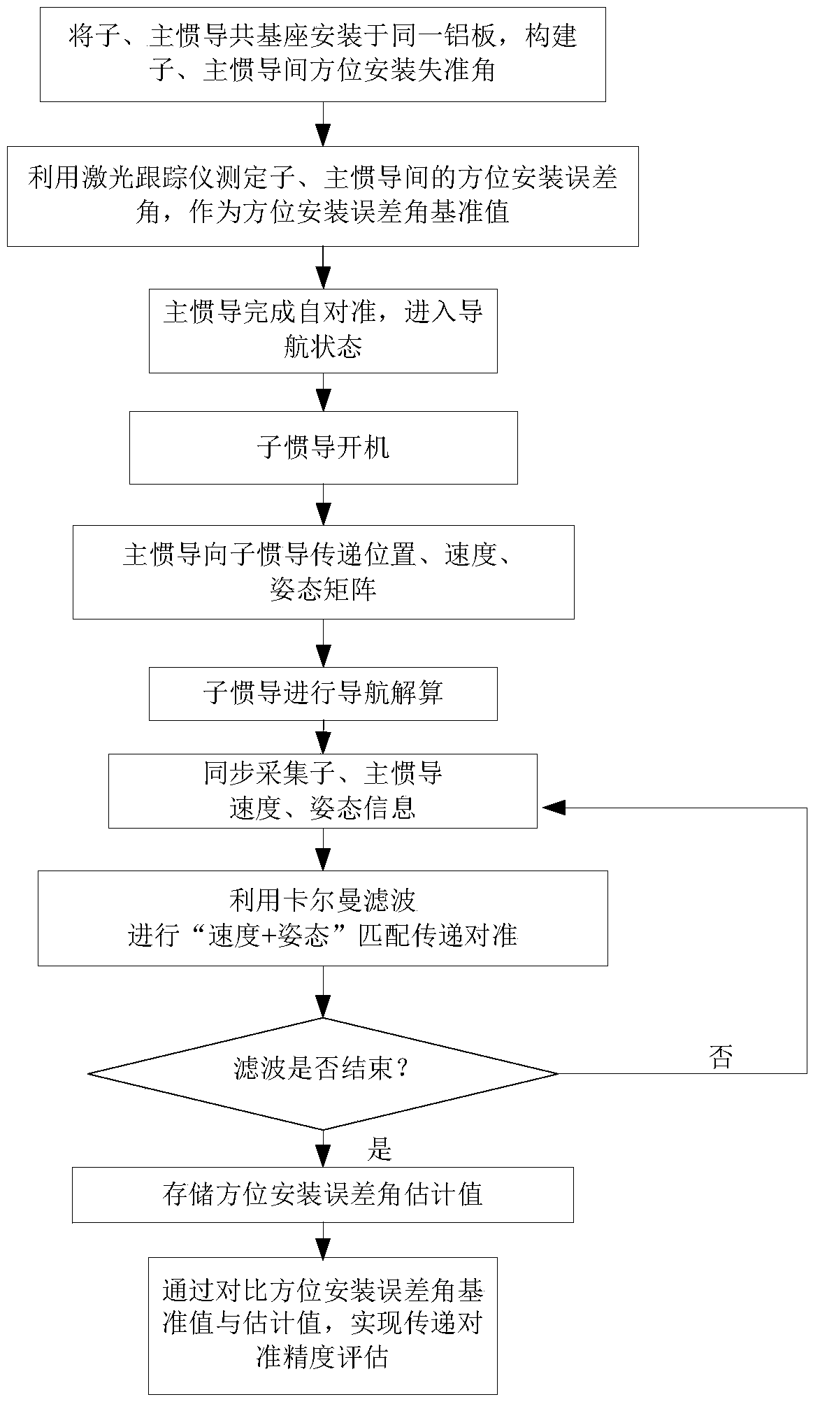
[0029] Realization of the present invention comprises the following steps:
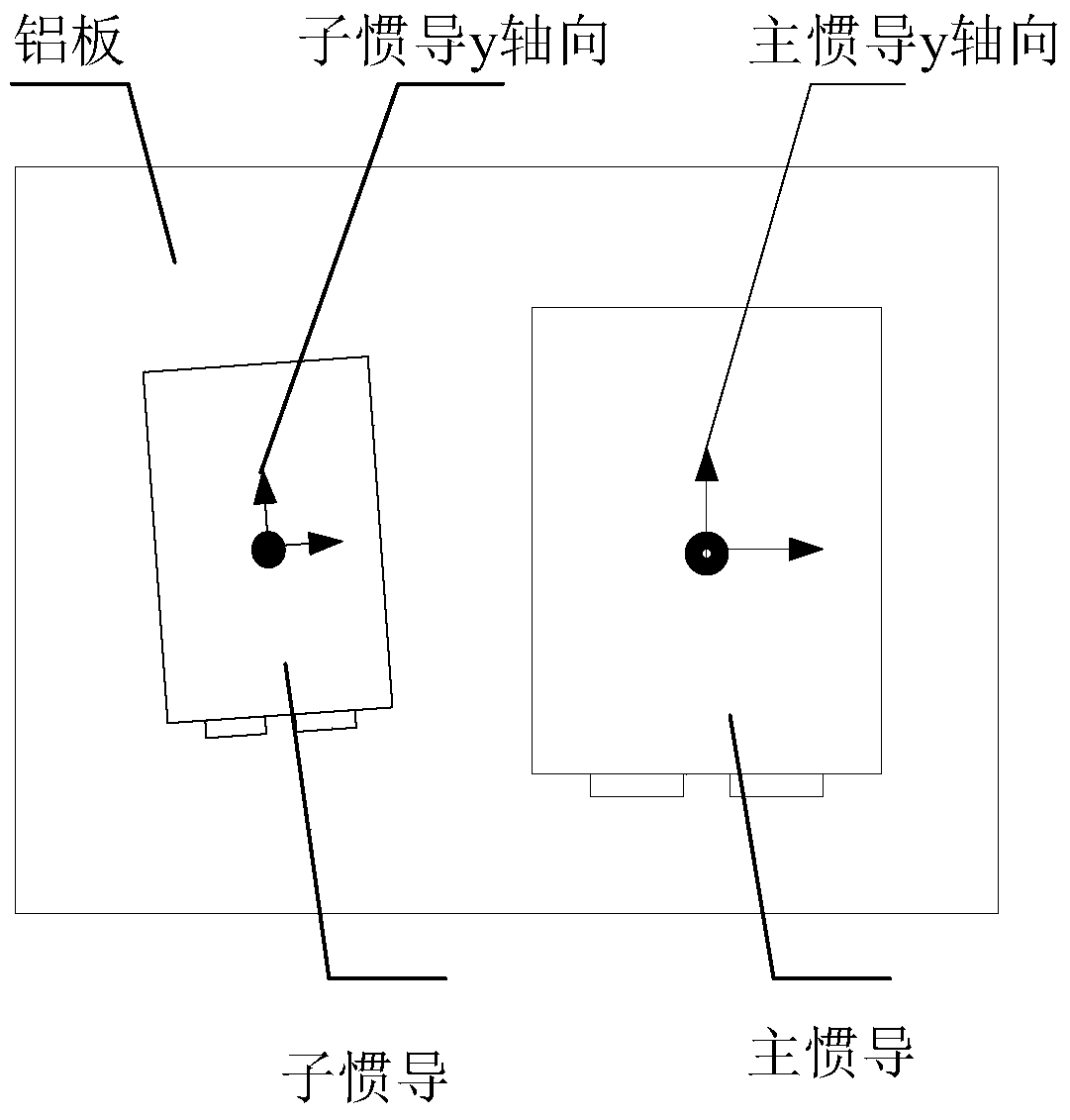
[0030] (1) Install the common base of the sub and main inertial navigation on the same aluminum plate, and construct the azimuth installation misalignment angle between the sub and main inertial navigation, so that the azimuth installation misalignment angle is less than or equal to 3 degrees;
[0031] (2) Place the aluminum plate with the sub- and main inertial navigation on the high-precision turntable, use the optical sight to make the y-axis of the main inertial navigation point to the north, and use the laser tracker to measure the distance between the sub- and main inertial navigation y-axis points The azimuth installation error angle is used as the reference value of the azimuth installation error angle;
[0032] (3) The main inertial navigation system starts up and completes self-alignment, and enters the navigation state;
[0033] (4) Sub-inertial navigation boot;
[0034] (5) The main iner...
Embodiment 2
[0046] Realization of the present invention comprises the following steps:
[0047] (1) Install the common base of the sub and main inertial navigation on the same aluminum plate, and construct the azimuth installation misalignment angle between the sub and main inertial navigation, so that the azimuth installation misalignment angle is greater than 3 degrees;
[0048] (2) Place the aluminum plate with the sub- and main inertial navigation on the high-precision turntable, use the optical sight to make the y-axis of the main inertial navigation point to the north, and use the laser tracker to measure the orientation between the sub- and main inertial navigation y-axis points The installation error angle is used as the reference value of the azimuth installation error angle;
[0049] (3) The main inertial navigation system starts up and completes self-alignment, and enters the navigation state;
[0050] (4) Sub-inertial navigation boot;
[0051] (5) The main inertial guide and...
PUM
 Abstract
Description
Claims
Application Information
 - R&D
- Intellectual Property
- Life Sciences
- Materials
- Tech Scout
- Unparalleled Data Quality
- Higher Quality Content
- 60% Fewer Hallucinations
Browse by: Latest US Patents, China's latest patents, Technical Efficacy Thesaurus, Application Domain, Technology Topic, Popular Technical Reports.
© 2025 PatSnap. All rights reserved.Legal|Privacy policy|Modern Slavery Act Transparency Statement|Sitemap|About US| Contact US: help@patsnap.com


