High-side/low-side effective signal detection circuit

An effective signal and detection circuit technology, applied in the direction of measuring electrical variables, measuring devices, instruments, etc., can solve the problems of high cost and poor flexibility of detection methods

Inactive Publication Date: 2016-09-28
ZHENGZHOU YUTONG BUS CO LTD
View PDF6 Cites 4 Cited by
  • Summary
  • Abstract
  • Description
  • Claims
  • Application Information

AI Technical Summary

Problems solved by technology

[0004] The purpose of the present invention is to provide a high-side and low-side effective signal detection circuit to solve the problems of poor flexibility and high cost of existing detection methods

Method used


Image

  • High-side/low-side effective signal detection circuit
  • High-side/low-side effective signal detection circuit

Examples


Embodiment Construction

[0014] The present invention will be described in further detail below in conjunction with the accompanying drawings.

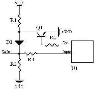
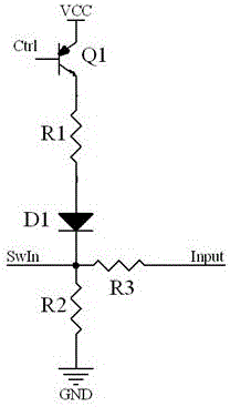
[0015] Such as figure 1 A detection circuit for high-side and low-side effective signals shown includes a microprocessor U1 for detection of low-side effective signals or high-side effective signals; the pin used for detection is the input I / O port Input . The output I / O port Ctrl of the microprocessor U1 is connected to a transistor Q1 under control, that is, the Ctrl is connected to the base of the transistor Q1 and can control the cutoff and conduction of the transistor Q1.

[0016] The detection circuit also includes a series circuit composed of a resistor R1, a diode D1, and a resistor R2 in sequence. The resistor R1 is a pull-up resistor, one end is connected to the power supply Vcc, the other end is connected to the anode of the diode D1, and connected to the collector of the transistor Q1; the cathode of the diode D1 is connected to the resistor R2,...


PUM


Abstract

The invention relates to a high-side/low-side effective signal detection circuit comprising a microprocessor (U1), an electronic switch (Q1) and a series circuit. The series circuit comprises a pull-up resistor (R1) and a grounding resistor (R2). One end of the grounding resistor (R2) is grounded, and the other end is connected with a signal input end (SwIn). One end of the pull-up resistor (R1) is connected with a power source, the other end of the pull-up resistor (R1) is connected with one end of the electronic switch, and the other end of the electronic switch is grounded. One output end (Ctrl) of the microprocessor (U1) is connected with the control end of the electronic switch, and one input end (Input) of the microprocessor (U1) is connected with the signal input end (SwIn). By configuring the state of the output level of the output port of the microprocessor, high-side input or low-side input detection of the same input port is realized.

Description

technical field [0001] The invention relates to a high-side and low-side valid signal detection circuit, that is, a valid state detection circuit which can detect both low-side valid signal and high-side signal valid. Background technique [0002] The digital input signal of the automotive ECU has both high-side input and low-side input. In order to adapt to different signals, there are generally two methods: one is to design hardware circuits according to actual needs; the other is to reserve ports. [0003] The first method has poor flexibility and is not conducive to platform applications. In the second way, reserving more ports will increase the cost and make the selection of connectors difficult. Contents of the invention [0004] The purpose of the present invention is to provide a high-side and low-side effective signal detection circuit to solve the problems of poor flexibility and high cost of the existing detection methods. [0005] To achieve the above object...

Claims


Application Information

Patent Timeline
Patent Type & Authority Applications(China)
IPC IPC(8): G01R29/00
CPCG01R29/00
Inventor 王永秋许广涛彭能岭李振山张永瑞李兴佳张永强李钰锐
Owner ZHENGZHOU YUTONG BUS CO LTD
Why Eureka
Try Eureka