Method and apparatus for uplink and/or downlink power control in a radio communication network

A downlink and power control technology, applied in the field of transmission power control, can solve the problems of no power and limited power, and achieve the effect of increasing power and spectral efficiency and improving overall throughput

Inactive Publication Date: 2016-09-28
TELEFON AB LM ERICSSON (PUBL)
View PDF4 Cites 0 Cited by
  • Summary
  • Abstract
  • Description
  • Claims
  • Application Information

AI Technical Summary

Problems solved by technology

In this case, it is very likely that the indoor UE becomes power limited as it approaches the c

Method used


Image

  • Method and apparatus for uplink and/or downlink power control in a radio communication network
  • Method and apparatus for uplink and/or downlink power control in a radio communication network
  • Method and apparatus for uplink and/or downlink power control in a radio communication network

Examples


Example Embodiment

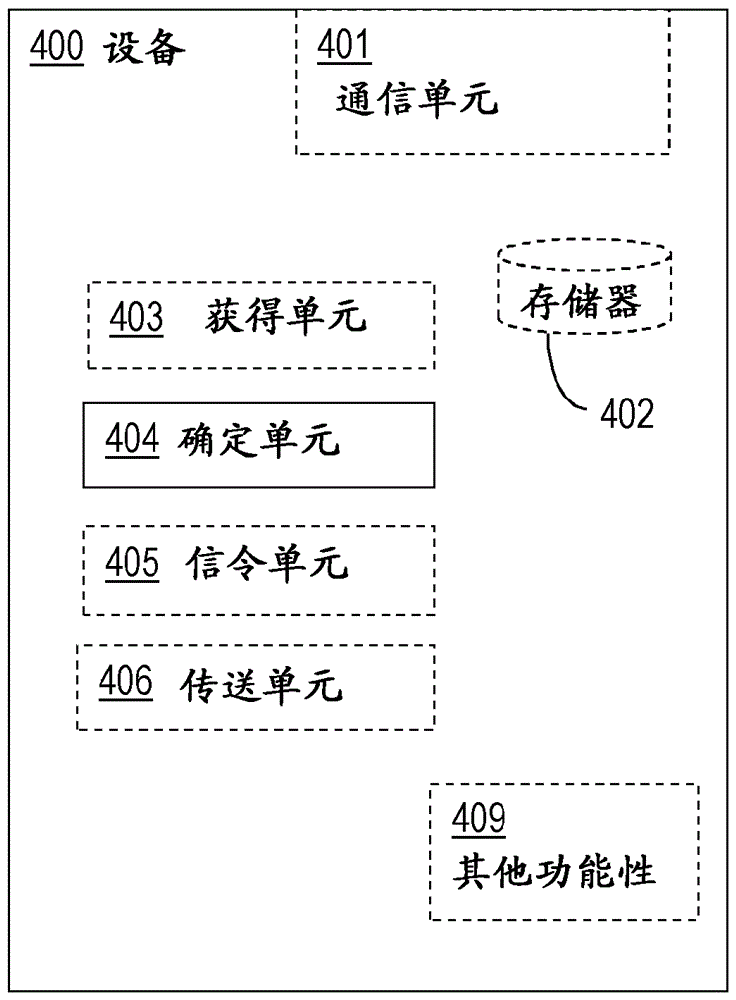
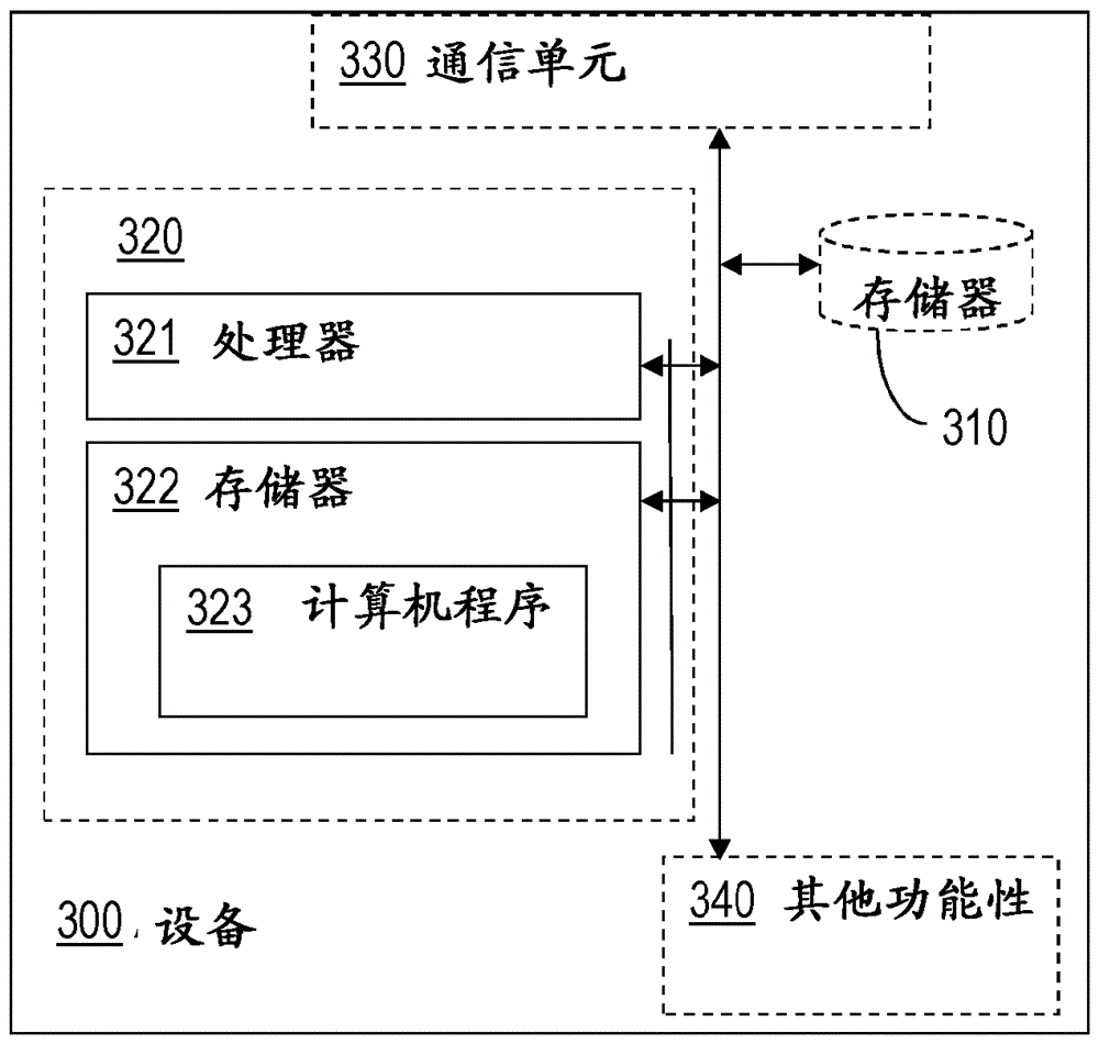
[0032] Briefly described, apparatus and methods performed thereby are provided for uplink and / or downlink power control in a radio communication network. The apparatus can be a wireless device and / or a wireless access point, and thus the method can be performed by a wireless device and / or a wireless access point. Non-limiting examples of wireless devices are UEs, mobile phones, laptop computers, personal digital assistants, or any other device comprising means for wirelessly communicating with a communication network via an access point. Non-limiting examples of wireless access points are radio base stations RBS, eNodeBs, base stations, base station controllers and radio network controllers.

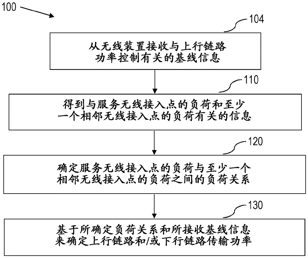
[0033] will now refer to Figure 1a -f to describe an embodiment of a method for uplink and / or downlink power control in a radio communication network. Fig. 1 is a flowchart of a method for uplink and / or downlink power control in a radio communication network according to an example emb...


PUM


Abstract

An apparatus and a method for uplink and/or downlink power control in a radio communication network are provided. The method comprises determining (120) a relationship between a load of a serving wireless access point and a load of at least one neighbouring wireless access point; and determining (130) an uplink or downlink transmission power based on the determined load relationship.

Description

technical field [0001] The present disclosure relates to transmission power control in uplink and / or downlink in a radio communication network. Background technique [0002] This disclosure relates to the field of uplink power control UL PC and downlink power control DL PC. UL PC and DL PC are coherent for several different radio access technologies RAT. The solutions described herein will be exemplified in relation to a Long Term Evolution LTE wireless network, but the solutions are also applicable to other types of wireless communication networks or RATs. [0003] In wireless communication networks, UL is usually a challenging link, where the scarce energy available to wireless devices, such as user equipment UE, must be used to compensate for channel losses (range-dependent path loss shadow fading, fast fading, etc.). Furthermore, the interference generated by any UL transmission in a multi-cell environment is another limiting factor for UL performance. One way to effi...

Claims


Application Information

Patent Timeline
IPC IPC(8): H04W52/34
CPCH04W52/343
Inventor C.考特斯马尼斯P.里奥里奥
Owner TELEFON AB LM ERICSSON (PUBL)
Why Eureka
Try Eureka