
Flying saucer

A flying saucer and saucer body technology, applied in the field of aircraft, to achieve the effect of small air resistance and good stealth effect

Active Publication Date: 2016-10-05
索宝元
View PDF6 Cites 4 Cited by
  • Summary
  • Abstract
  • Description
  • Claims
  • Application Information

AI Technical Summary

Problems solved by technology

[0002] At present, all fixed-wing aircraft have an insurmountable shortcoming, which is the need for a runway, and the faster the speed, the longer the runway, and the improvement of its structure and the update of its shape have also reached a bottleneck, so the development of new aircraft is imminent

Method used


Image

  • Flying saucer
  • Flying saucer
  • Flying saucer

Examples


Embodiment Construction

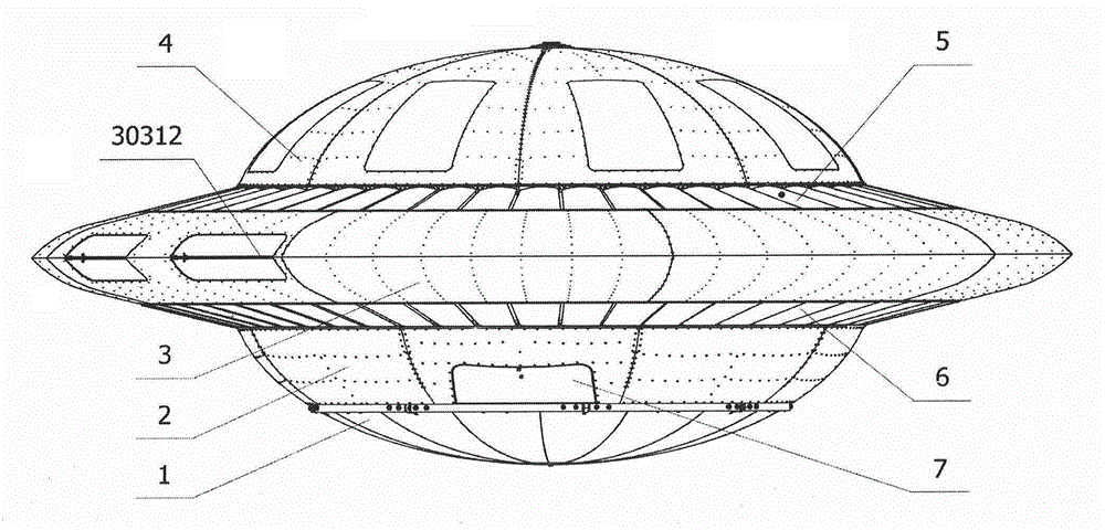
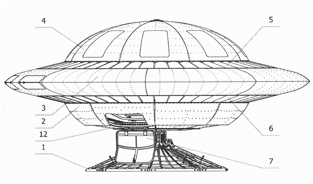
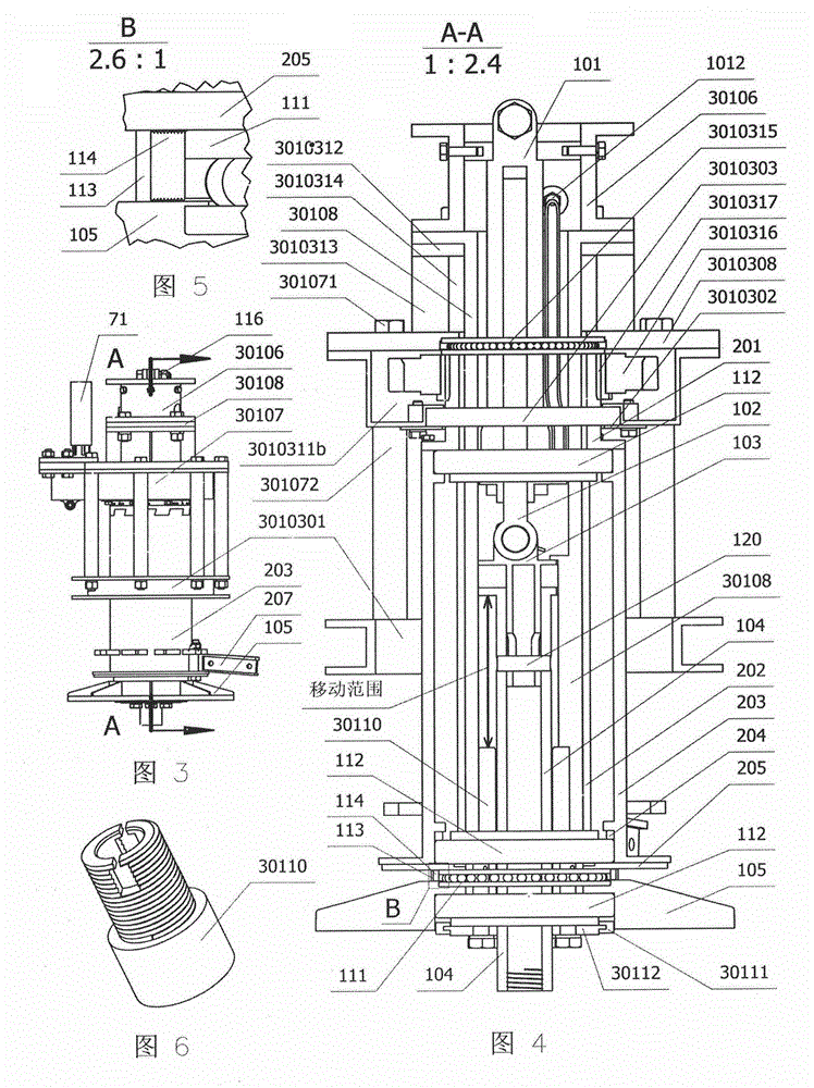
[0054] refer to Figure 1 to Figure 44 , the present invention comprises: landing gear 1, lower spin body 2, dish body 3, upper spin body 4, upper blade 5, lower blade 6, outer door 7, flight control system, described landing gear 1 closes against The bottom of the bottom spin body 2 is shaped like a spherical crown body, and its combined body and top spin body 4 are symmetrically distributed on the upper and lower sides of the side body. When landing, the undercarriage is shaped like a cone to support the flying saucer to land safely. Bottom spin body 2 is rotationally connected; the circular body in the middle of disc body 3 is the disc cabin, and the outer ring is the side body. The area between is the air flow channel that the rotating body drives the blades to rotate; the notch at the right fine-tuning plate 30803 of the side body is the air inlet, and the notch at the left fine-tuning plate 30312 is the air outlet; the lower rotating body 2 is installed Between the unde...


PUM


Abstract

A flying saucer comprises an undercarriage, a lower rotating body, a saucer body, an upper rotating body, upper blades, lower blades, an outer door and flying control systems, wherein the undercarriage nestles the lower portion of the lower rotating body after the flying saucer rises, a combination body of the flying saucer and the upper rotating body are symmetrically distributed on the upper side and the lower side of a side body, and the undercarriage supports the flying saucer to safely land like a cone when the flying saucer lands. A round body of the middle of the saucer body is a saucer cabin, and an outer ring is the side body. The top end and the lower portion outside the saucer cabin are respectively provided with the flying control systems, and a wind partition wall is arranged between the saucer cabin and the side body. The outer door is installed on the lower rotating body, the blades are installed on blade installing racks on the edges of the rotating bodies, and the upper rotating body and the lower rotating body drives the respective blades to rotate in mutually opposite directions. The flying saucer has the advantages that the saucer cabin, the rotating bodies, the blades and the side body are mutually connected to form a firm whole; the flying saucer takes off or lands like a helicopter, propels like an airplane and can complete step climbing, hovering, turnover, retrogradation and rotation at any angle only by changing attack angles of the upper blades and the lower blades.

Description

technical field [0001] The invention relates to an aircraft, in particular to a saucer-shaped aircraft, namely a flying saucer. Background technique [0002] At present, all fixed-wing aircraft have an insurmountable shortcoming, that is, they need a runway, and the faster the speed, the longer the runway, and the improvement of its structure and the updating of its shape have also reached a bottleneck, so the development of new aircraft is imminent. Contents of the invention [0003] For the above-mentioned shortcoming that fixed-wing aircraft exists, the present invention provides a kind of brand-new saucer-shaped aircraft, and subversive change has all taken place in its structural design, external shape, flight attitude; The future improvement and development space is unlimited. [0004] The technical solution of the present invention is: including landing gear, bottom spin body, dish body, top spin body, upper blade, lower blade, outer door, flight control system, it...

Claims


Application Information

Patent Timeline
Patent Type & Authority Applications(China)
IPC IPC(8): B64C39/06
Inventor 索宝元
Owner 索宝元
Learn More