A mechanical traction type unmanned aerial vehicle aerial retractable device
A technology of mechanical traction and retractable devices, which is applied in the direction of motor vehicles, aircraft parts, transportation and packaging, etc., can solve the problems of low reliability and electromagnetic interference of drones, achieve high reliability, improve flexibility and reliability , the effect of reducing weight and complexity
- Summary
- Abstract
- Description
- Claims
- Application Information
AI Technical Summary
Problems solved by technology
Method used
Image
Examples
specific Embodiment approach 1
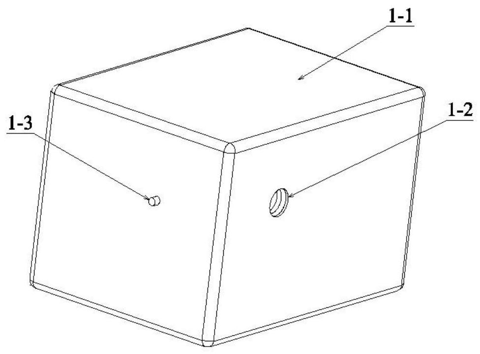
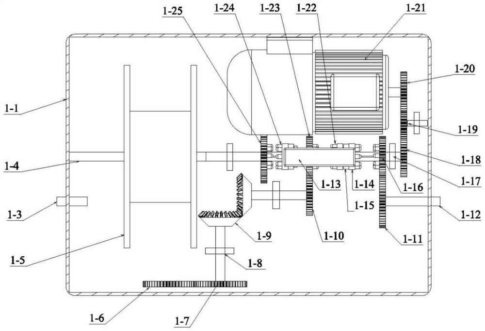
[0038] Embodiment 1: Combining Figure 1 to Figure 10 This embodiment will be described. A mechanical traction type unmanned aerial vehicle aerial retractable device of this embodiment includes a drive box 1, a mounting support 2, a rolling hard tube 3, a grabbing mechanical arm 4, a steel cable 5, an umbrella Cone 6 and drone 7, drive box 1 includes drive box shell 1-1, drive box transmission parts, winches 1-5, winch transmission parts, rolling hard pipe transmission parts, motors 1-21 and main transmission mechanism, drive The box shell 1-1 is rotatably connected to the lower part of the mounting support 2 through the drive box transmission. The mounting support 2 is installed at the tailgate of the transport aircraft or at the bombing port of the bomber, and the grabbing arm 4 is installed in the cabin of the transport aircraft or bomber. On the nacelle, the drive box shell 1-1 has a rectangular box-shaped structure, the front box plate of the drive box shell 1-1 is provid...
specific Embodiment approach 2
[0039] Specific implementation mode 2: Combining figure 1 , figure 2 and Figure 5 Describing this embodiment, the mounting support 2 of this embodiment includes a mounting plate 2-1 and two brackets 2-2, the two brackets 2-2 are symmetrically fixed on both sides of the mounting plate 2-1, and the two brackets 2-2 There are respectively two mounting holes 2-3 for the pitching shafts arranged opposite to each other. Other components and connection relationships are the same as in the first embodiment.
specific Embodiment approach 3
[0040] Specific implementation three: combination image 3 and Figure 4 Illustrating this embodiment, the main transmission mechanism of this embodiment includes a middle gear C1-20, a pinion 1-19, a pinion shaft, a pinion shaft supporting bearing, a middle gear B1-18, a main transmission shaft 1-17, two A main drive shaft support bearing, drive controller 1-13 and two shift paddles 1-15, the middle gear C1-20 is installed on the output shaft of the motor 1-21, and the main drive shaft 1-17 is horizontally arranged on the drive shaft Inside the box shell 1-1, two main drive shaft support bearing parts are vertically arranged side by side at the bottom of the box in the drive box shell 1-1, and the two ends of the main drive shaft 1-17 are respectively connected to the upper part of the two main drive shaft support bearing parts. Rotational connection, the middle gear B1-18 is installed on the right end of the main transmission shaft 1-17, the pinion gear 1-19 is installed on...
PUM
 Abstract
Description
Claims
Application Information
 - R&D
- Intellectual Property
- Life Sciences
- Materials
- Tech Scout
- Unparalleled Data Quality
- Higher Quality Content
- 60% Fewer Hallucinations
Browse by: Latest US Patents, China's latest patents, Technical Efficacy Thesaurus, Application Domain, Technology Topic, Popular Technical Reports.
© 2025 PatSnap. All rights reserved.Legal|Privacy policy|Modern Slavery Act Transparency Statement|Sitemap|About US| Contact US: help@patsnap.com


