Concealed airport power unit

A power unit and concealed technology, applied in the field of concealed airport power units, can solve problems such as hidden safety hazards, affecting the normal flight of aircraft, and alarming, and achieve the effect of reducing hidden safety hazards.

Pending Publication Date: 2021-04-06
沈阳精益液压技术有限公司
View PDF0 Cites 0 Cited by
  • Summary
  • Abstract
  • Description
  • Claims
  • Application Information

AI Technical Summary

Problems solved by technology

[0002] The power consumption of modern fighter jets is astonishing. In order to ensure the safety and efficiency of power consumption of fighter jets in the air, when the plane is stationary and fixed, the ground staff at the airport insert the cable plug into the lower part of the nose of the plane ( Some aircraft are on the external power plug on the front landing gear) and provide power, generally 115 volts three-phase alternating current, 28 volts direct current, the existing aircraft charging device is usually completed by the ground charging car at the airport, when the aircraft stops , drive the charging car to the bottom of the aircraft to charge the aircraft, but this charging car will affect the normal flight of other aircraft when it moves, and has certain safety hazards. In view of the above problems, a concealed airport power unit is needed , has solved the above-mentioned problems

Method used


Image

  • Concealed airport power unit
  • Concealed airport power unit
  • Concealed airport power unit

Examples


Embodiment Construction

[0016] The following will clearly and completely describe the technical solutions in the embodiments of the present invention with reference to the accompanying drawings in the embodiments of the present invention. Obviously, the described embodiments are only some, not all, embodiments of the present invention. Based on the embodiments of the present invention, all other embodiments obtained by persons of ordinary skill in the art without making creative efforts belong to the protection scope of the present invention.

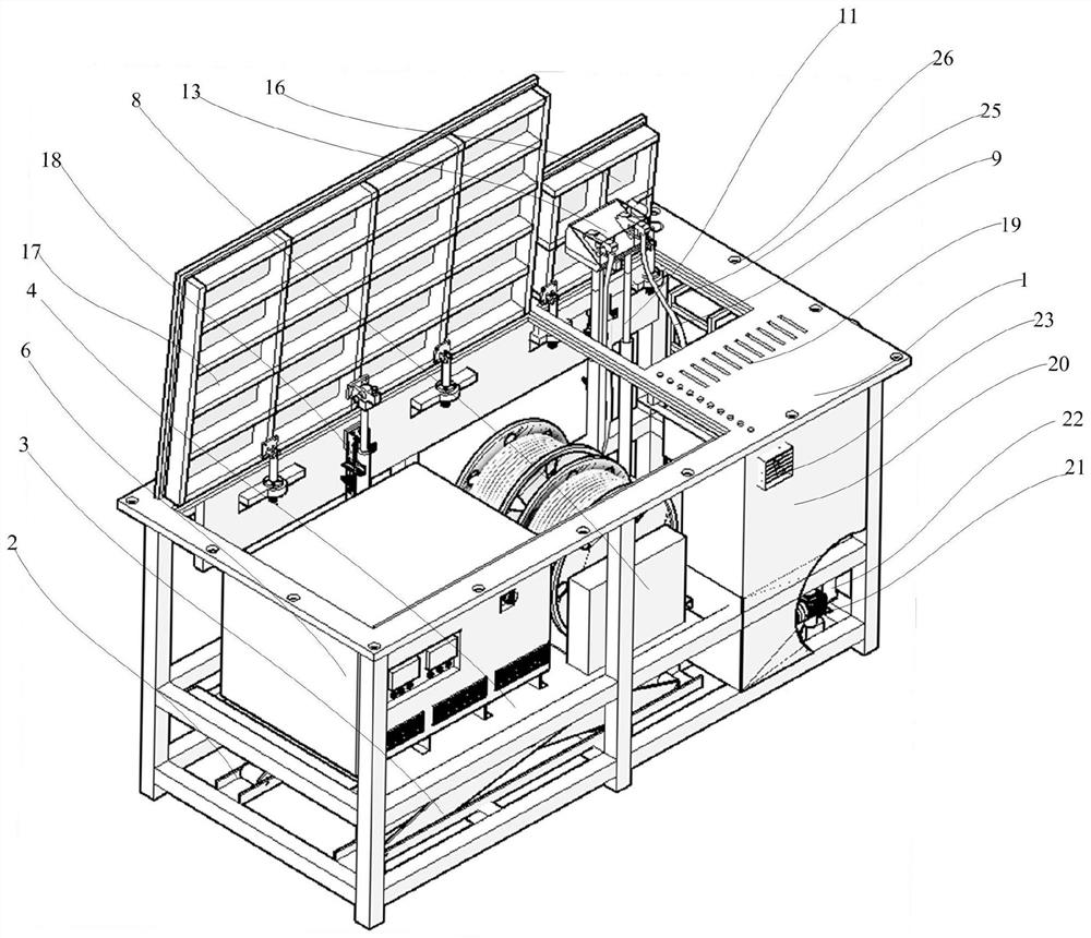
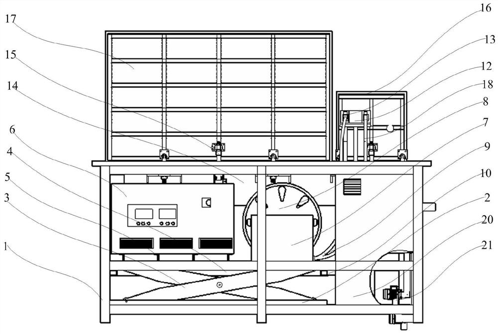
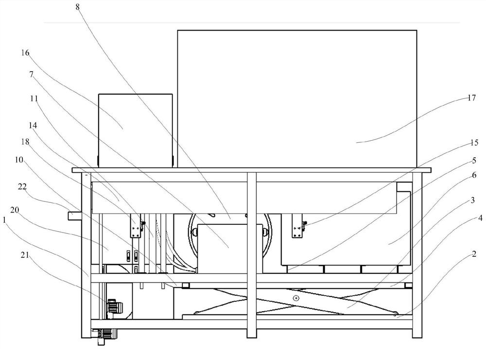
[0017] see Figure 1-4 , the present invention provides a technical solution: a concealed airport power unit, including a rectangular frame 1, the bottom of the rectangular frame 1 is fixedly connected with two slideways 2, the two slideways 2 are symmetrically arranged front and back, and the two slideways 2 The inner part is slidably connected with a hinged part, and the hinged part includes two mutually hinged support rods 3, the lower end of the support ro...


PUM


Abstract

The invention discloses a concealed airport power unit which comprises a rectangular frame, a hinge part slides at the bottom of the rectangular frame, a first supporting table is connected to the hinge part, a supporting frame is arranged on the first supporting table, a distribution box is connected to the supporting frame, a winding part is arranged on the first supporting table, the winding part comprises a wire spool, and a cable is arranged on the surface of the wire spool. A second supporting table is connected to the right end of the supporting table, a first hydraulic push rod is connected to the second supporting table, a supporting plate is connected to the first hydraulic push rod, a power unit connector is arranged on the surface of the supporting plate, a back plate is connected to the rectangular frame, and a second hydraulic push rod is arranged on the front portion of the back plate; the upper end of the rectangular frame is connected with a first cover plate; the upper end of the rectangular frame is rotatably connected with a second cover plate, the front portion of the back plate is provided with a third hydraulic push rod, the power unit can be hidden under the ground when not charged and can be lifted to charge an airplane when charged, great convenience is achieved, normal flight of the airplane in an airport cannot be affected, and potential safety hazards in the airport are reduced.

Description

technical field [0001] The invention relates to the technical field of power units, and specifically relates to a concealed airport power unit. Background technique [0002] The power consumption of modern fighter jets is astonishing. In order to ensure the safety and efficiency of power consumption of fighter jets in the air, when the plane is stationary and fixed, the ground staff at the airport insert the cable plug into the lower part of the nose of the plane ( Some aircraft are on the external power plug on the front landing gear) and provide power, generally 115 volts three-phase alternating current, 28 volts direct current, the existing aircraft charging device is usually completed by the ground charging car at the airport, when the aircraft stops , drive the charging car to the bottom of the aircraft to charge the aircraft, but this charging car will affect the normal flight of other aircraft when it moves, and has certain safety hazards. In view of the above problem...

Claims


Application Information

Patent Timeline
Patent Type & Authority Applications(China)
IPC IPC(8): B64F1/36B60L53/16B60L53/30B66F7/08B66F7/16B66F7/28
CPCB60L2200/10B64F1/36B66F7/065B66F7/08B66F7/16B66F7/28B60L53/16B60L53/30Y02T10/70Y02T10/7072Y02T90/12Y02T90/14
Inventor 张枫黄旌航王喆马兴邦孙亮李晓明
Owner 沈阳精益液压技术有限公司
Why Eureka
Try Eureka