Drainage structure of washing machine

A drainage structure and washing machine technology, applied in the field of washing machines, can solve the problems of slow start of dehydration, unable to discharge water in time, high moisture content of clothes, etc., and achieve the effect of convenient installation, good market promotion value, and simple structure

Active Publication Date: 2016-10-05
QINGDAO HAIER WASHING MASCH CO LTD
View PDF4 Cites 13 Cited by
  • Summary
  • Abstract
  • Description
  • Claims
  • Application Information

AI Technical Summary

Problems solved by technology

[0003] However, this type of washing machine with no holes in the bottom wall of the inner tub also has a disadvantage. Since the bottom of the inner tub is not provided with a dehydration drain hole, the water cannot be discharged in time during dehydration, the dehydration starts slowly, the vibration of the dehydration startup is large, and the energy consumption is high. Clothes with high moisture content

Method used


Image

  • Drainage structure of washing machine
  • Drainage structure of washing machine
  • Drainage structure of washing machine

Examples


Embodiment approach

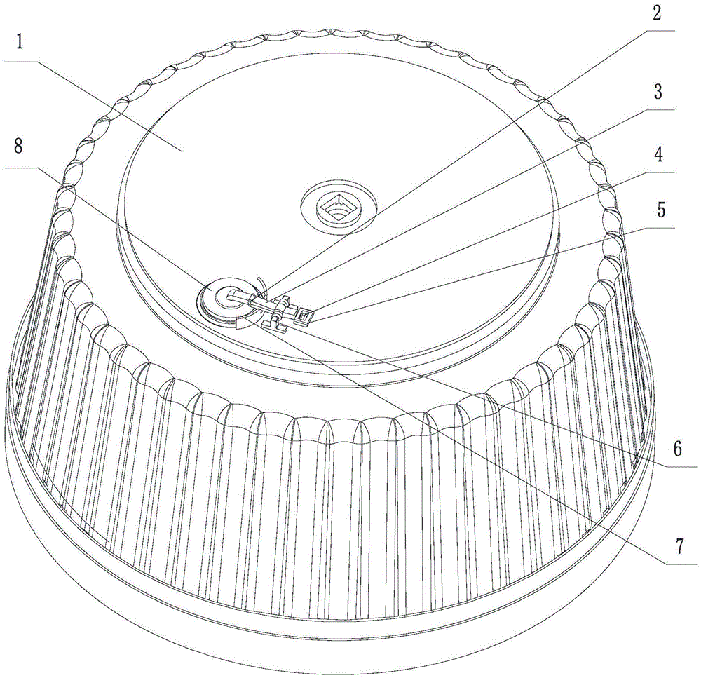
[0043] As a preferred embodiment of the present invention, the water sealing cover 8 is hingedly connected with the resistance arm end of the lever structure, the water sealing cover 8 can rotate freely around the center line of the resistance arm end of the lever structure, and the water sealing cover 8 and the inner barrel There is an included movable angle of 0-15° between the bottom walls, preferably, the included movable angle is 5°. Because the movement trajectory of the lever structure is a straight line, so when the water sealing cover 8 is covered on the drain, it is possible that a part will touch first while the other part has not been in contact, which will cause the drain cover to be lax and leak water. The drain cover 8 is used The hinged mode is connected to the lever structure, so that the sealing water cover 8 has a certain movable angle, which is more convenient for the water sealing cover 8 to cover the drain.

[0044] As a preferred embodiment of the presen...

Embodiment 1

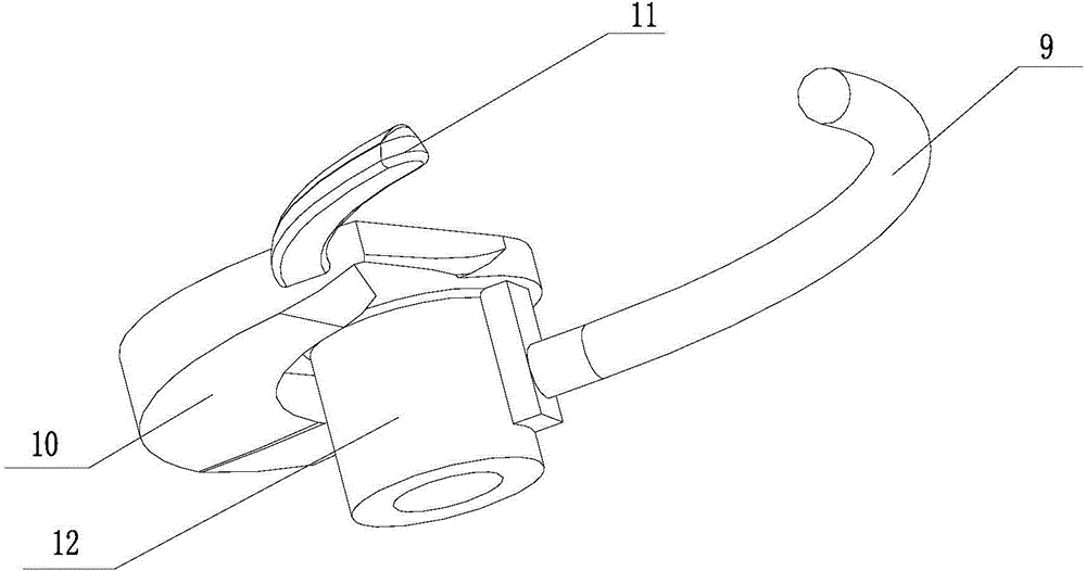
[0069] Such as figure 2 and image 3 As shown, the difference between this embodiment and the above-mentioned embodiment is that a kind of cam structure 12 suitable for the drainage structure of the washing machine of the present invention is provided. Since the cam 12 of the present invention is installed on the bottom wall of the inner tub 1 of the washing machine, as far as the installed position of the cam 12 is concerned, the contour curved surface is arranged on the upper surface of the cam 12 .

[0070] The cam 12 described in this embodiment is provided with a first lever 9 and a second lever 12, and the first lever 9 and the second lever 12 have a certain arc setting, and the center of the arc is located at the first stop lever assembly 16 and the second lever assembly. Second gear lever assembly 17 side. In this way, when the first lever assembly 16 and the second lever assembly 17 block the first lever 9 and the second lever 12, the first lever assembly 16 and th...

Embodiment 2

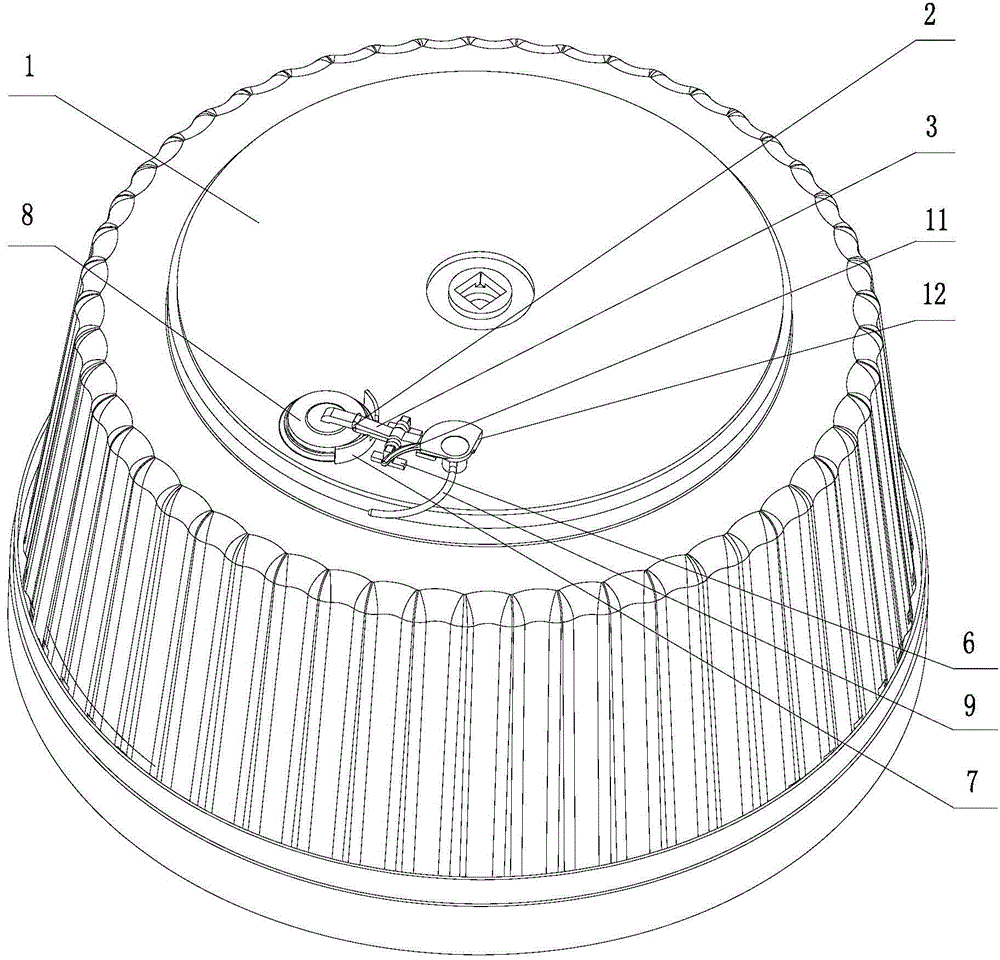
[0072] Such as Figure 12 and Figure 13 As shown, the difference between this embodiment and the above-mentioned embodiment is that a kind of cam structure 12 suitable for the drainage structure of the washing machine of the present invention is provided. Since the cam 12 of the present invention is installed on the bottom wall of the inner tub 1 of the washing machine, in terms of the installed position of the cam 12 , the curved surface 10 is arranged on the upper surface of the cam 12 .

[0073] The first driving rod 9 and the second driving rod 12 are arranged on the cam 12 described in this embodiment.

[0074] The cam 12 described in this embodiment is also provided with a first limiting portion 34 and a second limiting portion 35, the first limiting portion 34 is used to limit the rotation of the cam 12 to the position where the water sealing cover 8 opens the drain stop, the second limiting portion 35 is used to limit the rotation of the cam 12 to the position where...


PUM


Abstract

The invention provides a drainage structure of a washing machine, and no water exists between an inner barrel and an outer barrel of the washing machine when the washing machine is used for washing and rinsing. The washing machine comprises the inner barrel, no hole is formed in the lower portion of the side wall of the inner barrel, the drainage structure of the inner barrel comprises a water sealing cover, a lever structure and a drive device, the resisting arm end of the lever structure is connected with the water sealing cover, the power arm end of the lever structure is provided with the drive device for driving the lever structure to work, the bottom wall of the inner barrel is provided with a drainage opening, and the lever structure is driven by the drive device to drive the water sealing cover to close the drainage opening in the washing and rinsing processes and to open the drainage opening in the drainage process. According to the drainage structure, ascending and descending of the resisting arm end of the lever structure are utilized to drive the water sealing cover to close or open the drainage opening, drainage is achieved, and the drainage structure of the washing machine is simple in structure and convenient to mount and has high market popularization value.

Description

technical field [0001] The invention relates to the technical field of washing machines, in particular to a washing machine drainage structure. Background technique [0002] With the improvement of living standards, people have higher and higher requirements for washing machines. Simple laundry can no longer meet the requirements of customers, especially energy and development have become the theme of social development. While meeting people's basic laundry requirements, washing machines , Energy saving has also become an important factor in measuring washing machines. When a common pulsator washing machine is filled with water, there is a large amount of water between the inner tub and the outer tub, and the water outside the inner tub is wasted during washing. There is an existing washing machine with no holes in the lower part of the inner tub. This kind of washing machine only has a dehydration drain hole on the upper end of the inner tub. After water injection, when wa...

Claims


Application Information

Patent Timeline
Patent Type & Authority Applications(China)
IPC IPC(8): D06F39/08D06F37/30
CPCD06F39/083D06F37/12D06F39/08D06F37/267D06F23/04D06F2105/08
Inventor 吕佩师杨林张刚金田云刘建设
Owner QINGDAO HAIER WASHING MASCH CO LTD
Why Eureka
Try Eureka