High-pressure gas cylinder structure for inflation

A high-pressure gas cylinder and gas cylinder technology are applied in pressure vessels, fixed-capacity gas storage tanks, and container discharge methods, etc., and can solve the problems of waste and environmental protection, easy to cause safety problems, and uneconomical practicability.

Inactive Publication Date: 2016-10-05
黄 仲伟 +2
View PDF5 Cites 0 Cited by
  • Summary
  • Abstract
  • Description
  • Claims
  • Application Information

AI Technical Summary

Problems solved by technology

[0002] Press, today's disposable high-pressure air cylinders can be carried by users, and can be used to inflate bicycle rims. Its bottle body 90 and valve body 91 are separate (such as Figure 8 As shown), it is used directly after opening the valve body 91, but because the high-pressure gas is stored inside the disposable high-pressure gas cylinder, it has not been properly decompressed, so it is easy to cause safety problems during use
[0003] Moreover, after these disposable high-pressure gas cylinders are used, the empty bottle body 90 is directly discarded, so that waste and environmental protection problems are caused, and it is not economically practical; There are various deficiencies, and it is necessary to further improve it

Method used


Image

  • High-pressure gas cylinder structure for inflation
  • High-pressure gas cylinder structure for inflation
  • High-pressure gas cylinder structure for inflation

Examples


Embodiment Construction

[0052] The drawings of the preferred embodiments of the present invention are further described below in order to enable those familiar with the relevant technologies of the present invention to implement according to the statements in this specification.

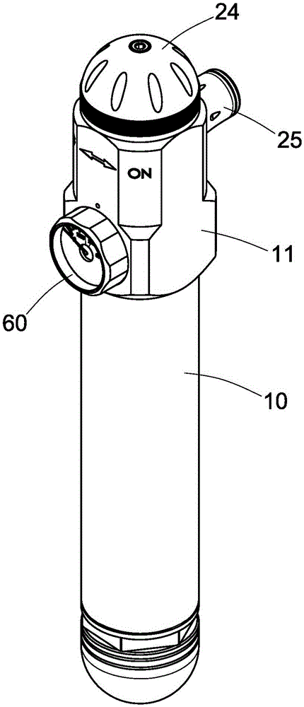
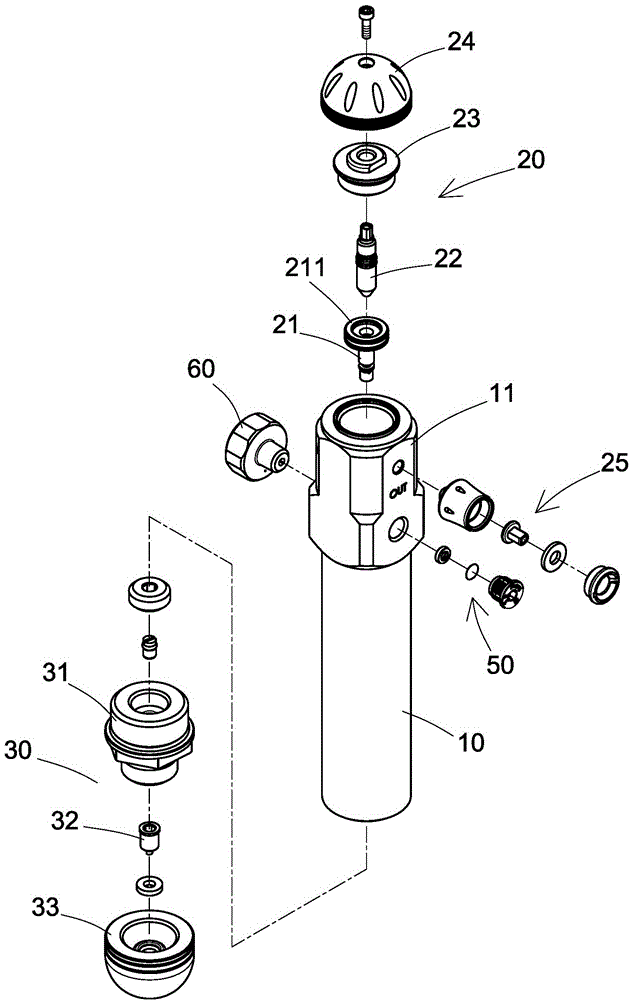
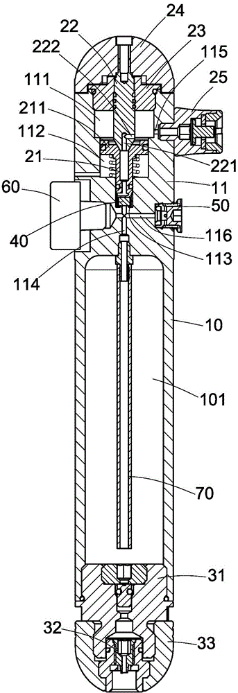
[0053] First, please refer to Figure 1 to Figure 7 As shown, it is a high-pressure gas cylinder structure suitable for inflating gas, which includes:

[0054] A gas cylinder body 10, the gas cylinder body 10 has a gas storage space 101 that can be filled with high-pressure gas, the top of the gas cylinder body 10 has a connecting portion 11 integrally formed with the gas cylinder body 10, the connecting portion 11 The interior has a first chamber 111, a second chamber 112, a third chamber 113 and an air guide channel 114 in axial communication, and the air guide channel 114 communicates with the gas storage space 101;

[0055] A decompression assembly 20, the decompression assembly 20 is mounted on the connecting portion ...


PUM


Abstract

The invention provides a high-pressure gas cylinder structure for inflation. The high-pressure gas cylinder structure comprises a gas cylinder body, a decompression component and an inflation component; the gas cylinder body comprises a connecting part, the connecting part comprises a first cavity, a second cavity, a third cavity and a gas guiding pipe which are communicated to a gas storage space with axial communication, the decompression component is arranged at a connection part of the gas cylinder body, a fixed pressing shaft is accommodated into the third cavity, an upper cover is fixedly arranged at one end of a push rod, the upper cover is arranged at top edge of the first cavity, one end of the upper cover presses against a top surface of a projection part of the fixed pressing shaft, a first gas outlet communicated to the first cavity is arranged at periphery of the connecting part, the inflation component is arranged at the bottom of the gas cylinder body, a fixing sleeve is fixedly arranged at the bottom of the gas cylinder body, one end of a fixing sleeve is used for accommodating an one-way valve, outer periphery is used for fixedly arranging a protective sleeve; the high pressure gas can be reduced pressure, and a certain of usage pressure is kept, the high pressure gas has the advantages of safe usage performance, light volume, and convenient carrying, and can be used for repetitive high-pressure gas filling, and has environmental protection practical performance.

Description

technical field [0001] The present invention relates to a high-pressure gas cylinder structure suitable for inflating gas, especially a high-pressure gas cylinder structure capable of decompressing high-pressure gas and maintaining a certain operating pressure, and can be repeatedly filled with high-pressure gas. Background technique [0002] Press, today's disposable high-pressure air cylinders can be carried by users, and can be used to inflate bicycle rims. Its bottle body 90 and valve body 91 are separate (such as Figure 8 As shown), it is used directly after opening the valve body 91, but because the high-pressure gas is stored inside the disposable high-pressure gas cylinder, it has not been properly decompressed, so it is easy to cause safety problems during use. [0003] Moreover, after these disposable high-pressure gas cylinders are used, the empty bottle body 90 is directly discarded, so that waste and environmental protection problems are caused, and it is not ec...

Claims


Application Information

Patent Timeline
IPC IPC(8): F17C1/00F17C13/00F17C13/02
Inventor 黄仲伟李文宏黄承毓
Owner 黄 仲伟
Why Eureka
Try Eureka