Tunnel full-face diversion waterproof structure and construction method thereof

A waterproof structure and full-section technology, which is applied in tunnels, tunnel linings, drainage, etc., can solve the problems of increasing engineering volume and cost of grouting and water blocking, and achieves the effect of simple installation and splicing, convenience and practicability

Active Publication Date: 2019-10-25
NORTHEASTERN UNIV
View PDF5 Cites 0 Cited by
  • Summary
  • Abstract
  • Description
  • Claims
  • Application Information

AI Technical Summary

Problems solved by technology

If all grouting is blocked, it will increase the engineering quantity and the cost of grouting water plugging

Method used


Image

  • Tunnel full-face diversion waterproof structure and construction method thereof
  • Tunnel full-face diversion waterproof structure and construction method thereof
  • Tunnel full-face diversion waterproof structure and construction method thereof

Examples


Embodiment 1

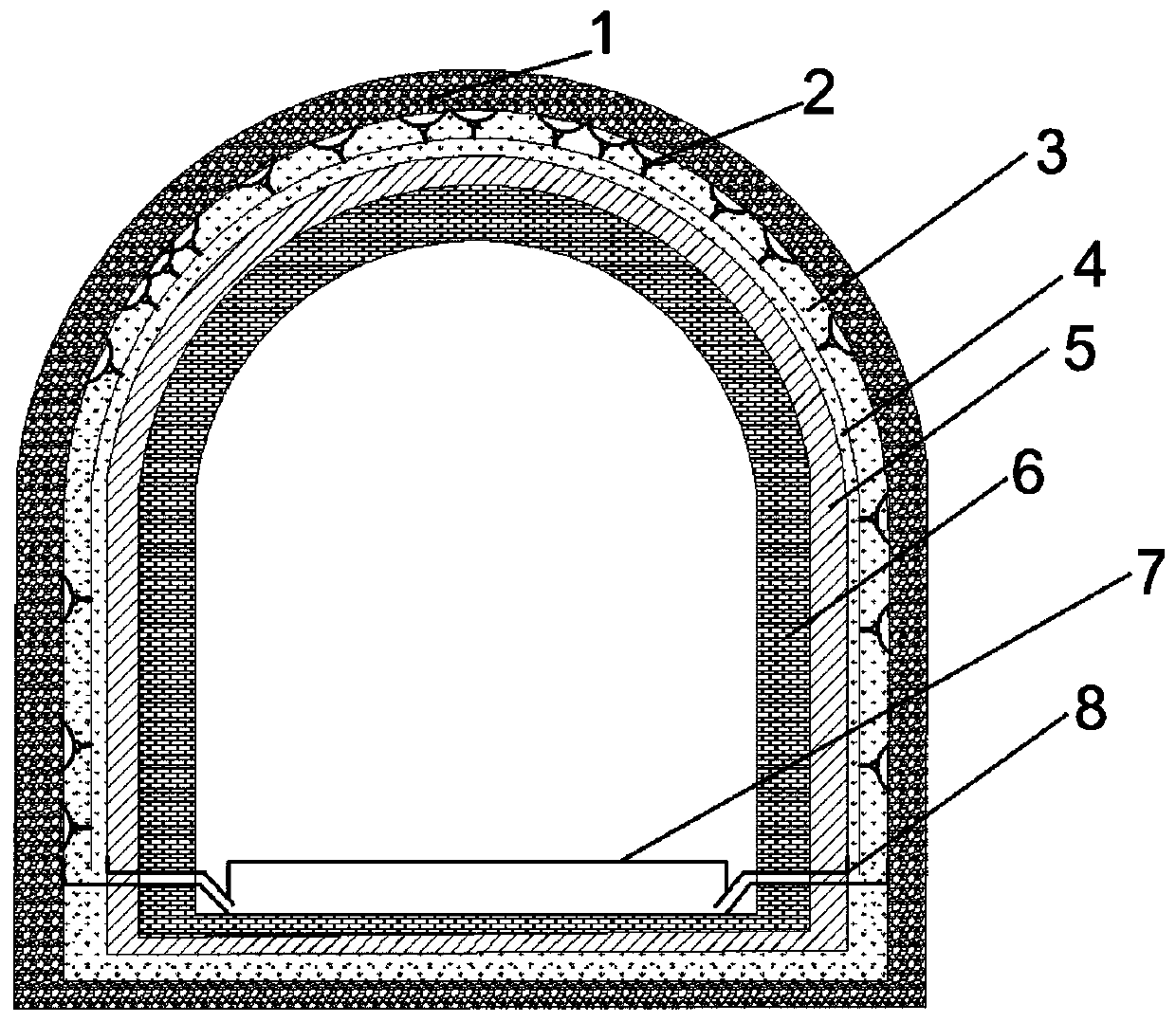
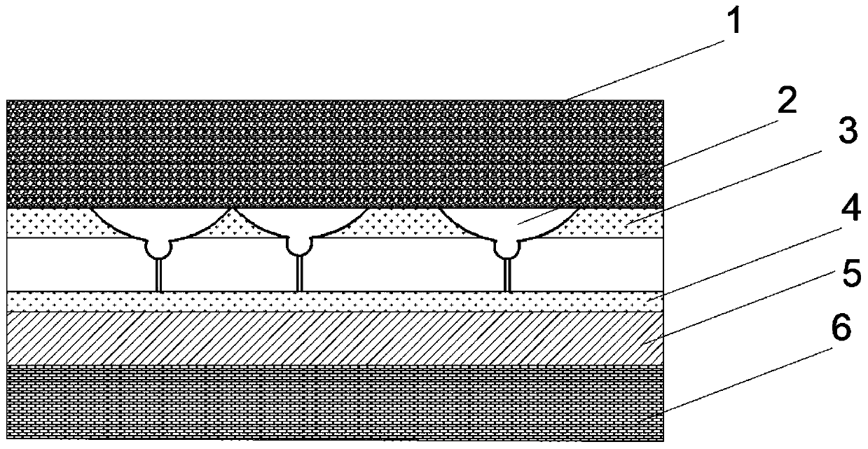
[0036] A drainage and waterproof structure for the full section of a tunnel, comprising a tunnel excavation profile layer 1, a water collection system 2, a primary support concrete layer 3, a water delivery system 4, a secondary lining waterproof layer 5, a secondary lining pouring layer 6, and a tunnel floor 7, gutter 8.

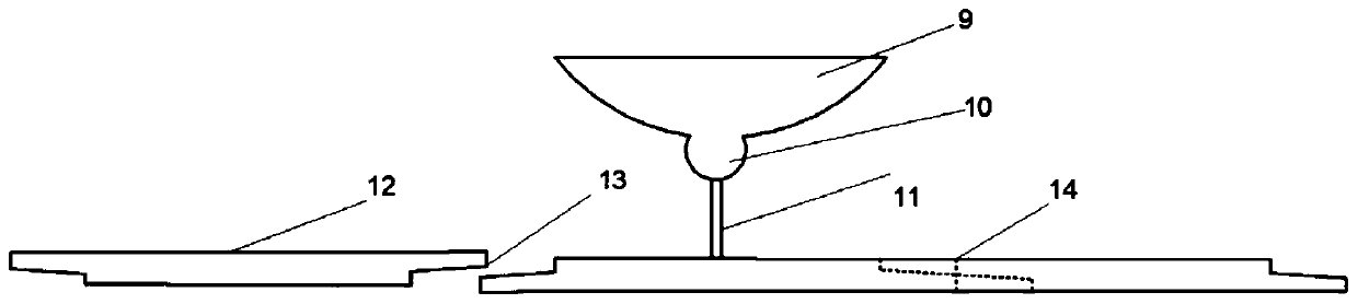
[0037] The water collecting system 2 is composed of a water collecting pan 9, a steering ball 10 and a steel pipe 11.

[0038] in:

[0039] The diameter of the outermost edge of the water collection tray 9 is 0.4m. The steering ball 10 is integrated with the water collection tray 9. The material is polyurethane rubber. The steering ball 10 has high toughness and elasticity; the upper and lower ends of the steel pipe 11 are threaded, and the diameter of the steel pipe is 5cm. The length is 0.25m, and it is used to connect the water collection system 2 and the hollow PVC board 12 for water delivery.

[0040] The position of the water collection tray 9 can b...

Embodiment 2

[0051] The construction method of the drainage and waterproof structure of the full section of the tunnel, the steps are as follows:

[0052]1) The construction drainage tank 8 is made of concrete.

[0053] 2) Record and analyze the cracks and water seepage of the tunnel excavation contour layer. Set appropriately more water collecting pans 9 at positions with dense cracks and large water seepage, and set appropriately less water collecting pans at positions with sparse cracks and small water seepage. water tray9. The diameter of the outermost edge of the water collection tray 9 is 0.4m, and the steering ball 10 is integrated with the water collection tray 9. The material is polyurethane rubber, and the steering ball 10 has high toughness and elasticity. The water collecting tray 9 is fixed through the primary support concrete layer 3 . A gap of about 7 cm is maintained between the primary concrete layer 3 and the water delivery system 4 .

[0054] 3) According to the posit...


PUM

PropertyMeasurementUnit
Outer diameteraaaaaaaaaa
Diameteraaaaaaaaaa
Lengthaaaaaaaaaa

Abstract

The invention relates to a tunnel full-face diversion waterproof structure and a construction method thereof. A water collection disc and a steering ball are integrated, a threaded connection steeringball and a water transmission hollow PVC plate are arranged at an upper end and a lower end of a steep pipe, a water transmission system comprises a plurality of water transmission hollow PVC plates,a water collection system and the water transmission system jointly form a diversion structure, two lining waterproof layers are arranged at a lower end of the water transmission system, two lining casting layers form a bearing rack by reinforced concrete and are arranged at lower ends of the two lining waterproof layers, a tunnel bottom plate is laid in a tunnel, one end of a drainage groove penetrates into a lower end of the tunnel bottom plate and is connected with a drainage ditch, the other end of the drainage groove penetrates out of the two lining casting layers, two waterproof layersare inserted into the water transmission system of an initial concrete layer, water seepage of a surrounding rock can flow into the water transmission system by the water collection system, and waterin the water transmission system can flow into the drainage groove and is finally discharged into the drainage ditch of the tunnel bottom plate. By the scheme, the water pressure of the tunnel surrounding rock is reduced, the stability of the tunnel surrounding rock is improved, the engineering quantity is also reduced, and grouting and water plugging cost is reduced.

Description

technical field [0001] The invention belongs to the technical field of tunnel waterproof drainage and construction, and in particular relates to a tunnel full-section drainage waterproof structure and a construction method thereof. Background technique [0002] Complicated hydrogeological and engineering geological conditions are often encountered in tunnel engineering construction. Building tunnels in rock masses with abundant groundwater and many fissures will face the problems of drainage, waterproofing and surrounding rock stability. [0003] In dealing with the stability of the surrounding rock, it is necessary to remove dangerous rock masses and potentially falling rock masses and support dangerous blocks. In terms of dealing with water seepage in surrounding rocks, grouting should be injected in time to block water at faults where water seepage is large, and grouting should also be used for water blocking where cracks are densely distributed. However, in water-rich ...

Claims


Application Information

Patent Timeline
IPC IPC(8): E21D11/38E21F16/02E21D11/10
CPCE21D11/10E21D11/38E21F16/02
Inventor 王述红刘欢王鹏宇修占国
Owner NORTHEASTERN UNIV
Why Eureka
Try Eureka