Stepping motor driving device and timepiece

A technology of stepping motor and driving device, applied in clocks, electromechanical clocks, electric winding, etc., can solve the problems of accelerating battery consumption and increasing power.

Active Publication Date: 2016-10-05
CASIO COMPUTER CO LTD
View PDF4 Cites 0 Cited by
  • Summary
  • Abstract
  • Description
  • Claims
  • Application Information

AI Technical Summary

Problems solved by technology

However, the electric energy consumed by the internal resistance of the battery etc. is proportional to the square of the current consumption, so according to the technique of the above-mentioned patent document, the electric power consumed during the latter period becomes large, and there is a problem of accelerating the consumption of the battery.

Method used


Image

  • Stepping motor driving device and timepiece
  • Stepping motor driving device and timepiece
  • Stepping motor driving device and timepiece

Examples


no. 1 Embodiment approach

[0015] (the whole frame)

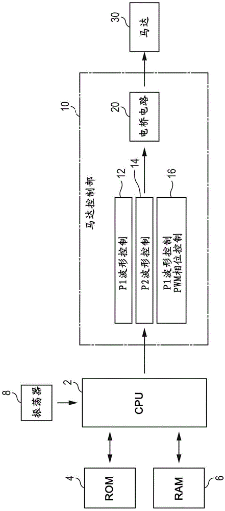
[0016] Next, refer to figure 1 The shown block diagram explains in detail the stepping motor drive device according to the first embodiment of the present invention.

[0017] exist figure 1 Among them, a CPU (Central Processing Unit) 2 outputs various commands to the motor control unit 10 based on a control program stored in a ROM (Read Only Memory) 4 . RAM (Random Access Memory) 6 is used as the working memory of CPU2. An oscillator (referred to as "OSC") 8 outputs an operating clock pulse to the CPU 2 .

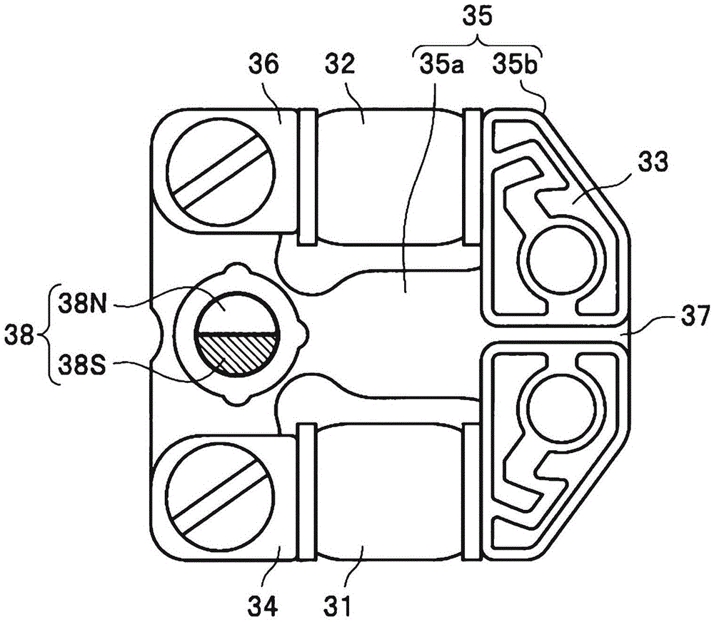
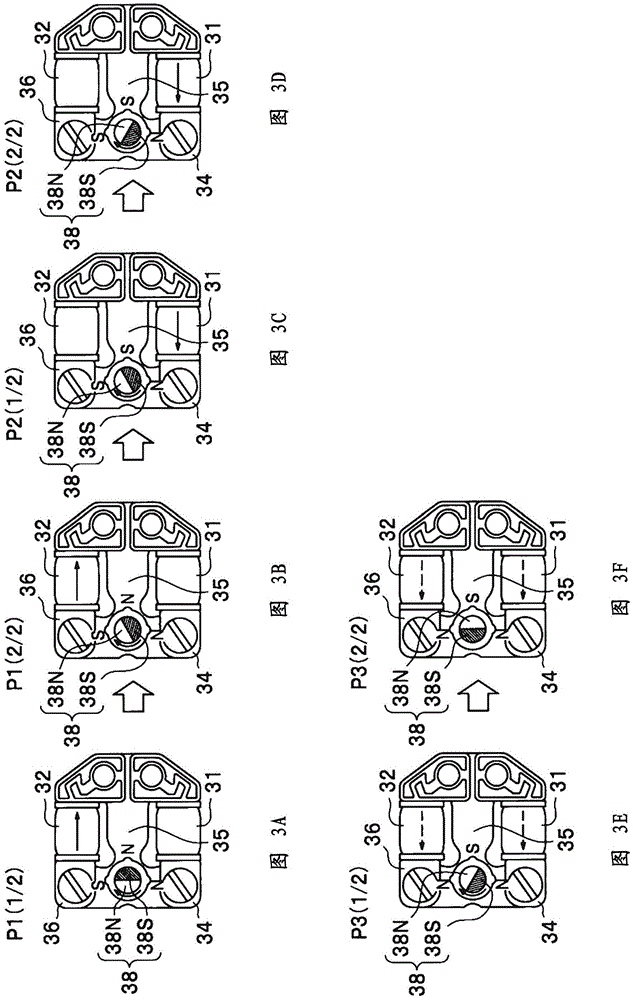
[0018] The stepping motor 30 has a rotor with permanent magnets and a stator with two coils. The bridge circuit 20 in the motor control unit 10 drives the stepping motor 30 by applying a square wave or PWM (pulse width modulation) modulated voltage to these two coils. In the driving state of the stepping motor 30 , there are three phases of phases P1 , P2 , and P3 , which will be described later. The P1 waveform control unit 12 , the P2 wave...

no. 2 Embodiment approach

[0047] Next, refer to Figure 8 The plan view shown is an explanation of an analog timepiece according to a second embodiment of the present invention.

[0048] exist Figure 8 Among them, the analog timepiece 500 has: a dial 501 , and two hands (hour hand and minute hand) 502 that rotate on the dial 501 around a pointer axis 504 . In addition, two stepping motors 30 are installed on the back side of the dial 501 corresponding to the two pointers 502 , and the corresponding pointers 502 are rotationally driven via respective needle movement mechanisms 503 .

[0049] These stepping motors 30 are the same as the stepping motors 30 described in the first embodiment, and are composed of figure 1 Driven by the stepper motor driver shown. It also goes without saying that more hands can be provided on the analog timepiece 500. According to this embodiment, using the stepping motor drive device of the first embodiment ( figure 1 ) rotates the pointer 502, so that the peak value o...


PUM


Abstract

The present invention provides a stepping motor driving device, which has a first coil and a second coil, a motor control unit (10) is provided in the stepping motor driving device, and a predetermined voltage is applied to the first coil in the first phase; The second phase subsequent to the second phase applies a predetermined voltage to the second coil; the third phase subsequent to the second phase applies a predetermined voltage to the first coil and the second coil alternately.

Description

technical field [0001] The invention relates to a stepping motor driving device and a clock. Background technique [0002] Conventionally, stepping motors configured to be reversible in forward and reverse directions have been used in timepieces and the like. For example, the stepping motor disclosed in Japanese Patent Application Laid-Open No. 2014-195371 includes: a rotor with 2-pole excitation, 3 magnetic poles arranged at intervals of 90° around the rotor, and a motor wound around 2 of the 3 magnetic poles. coil. Then, the stepping motor is rotationally driven by appropriately applying drive pulses to these two coils. [0003] According to the technique of the above-mentioned patent document, when rotating the stepping motor, there are periods in which power is supplied to only one of the two coils and periods in which power is supplied to both of the two coils. At this time, a peak value of consumption current (current output from the battery) appears during the latt...

Claims


Application Information

Patent Timeline
Patent Type & Authority Applications(China)
IPC IPC(8): H02P8/12
CPCH02P8/12G04C3/143G04C3/146H02P8/02
Inventor 川口洋平齐藤雄太
Owner CASIO COMPUTER CO LTD
Why Eureka
Try Eureka