Frequency-division multiplexing transceiver apparatus and method

A frequency division multiplexing and transmission device technology, applied in the field of frequency division multiplexing transceiver devices, can solve the problem of not reducing the PAPR of the transmission signal, and achieve the effect of reducing PAPR and suppressing the peak value

Inactive Publication Date: 2007-08-22
FUJITSU LTD
View PDF2 Cites 3 Cited by
  • Summary
  • Abstract
  • Description
  • Claims
  • Application Information

AI Technical Summary

Problems solved by technology

[0042] However, in this prior art, the PAPR of the transmitted signal is not degraded in the IFDMA modulation method

Method used


Image

  • Frequency-division multiplexing transceiver apparatus and method
  • Frequency-division multiplexing transceiver apparatus and method
  • Frequency-division multiplexing transceiver apparatus and method

Examples


no. 1 example

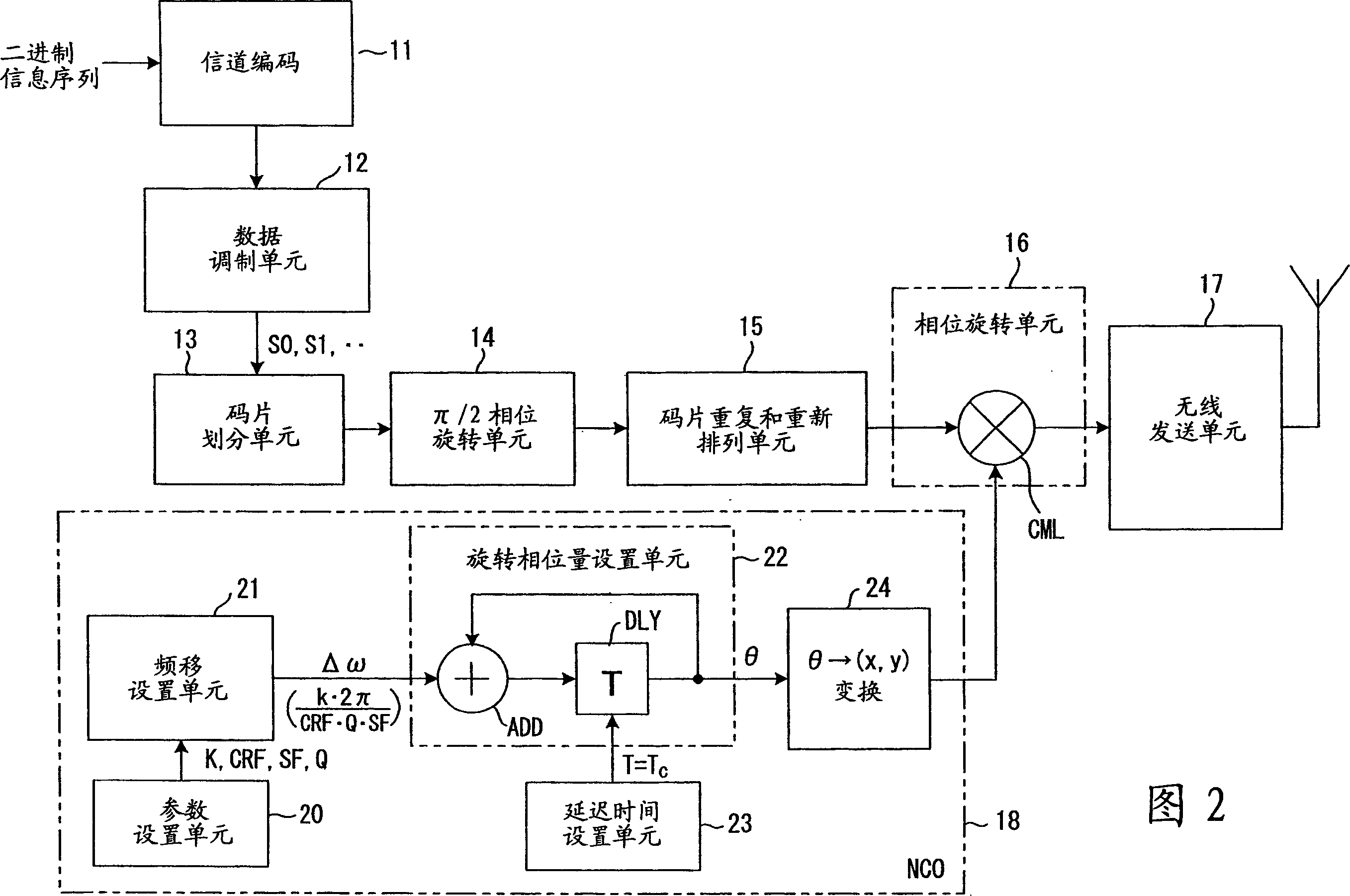
[0104]FIG. 2 is a block diagram of a frequency division multiplexing transmission device of the first embodiment of the present invention, and FIG. 3 is a diagram for explaining the operation of the frequency division multiplexing transmission device. The frequency division multiplexing transmission apparatus of this first embodiment can be used as a mobile station.

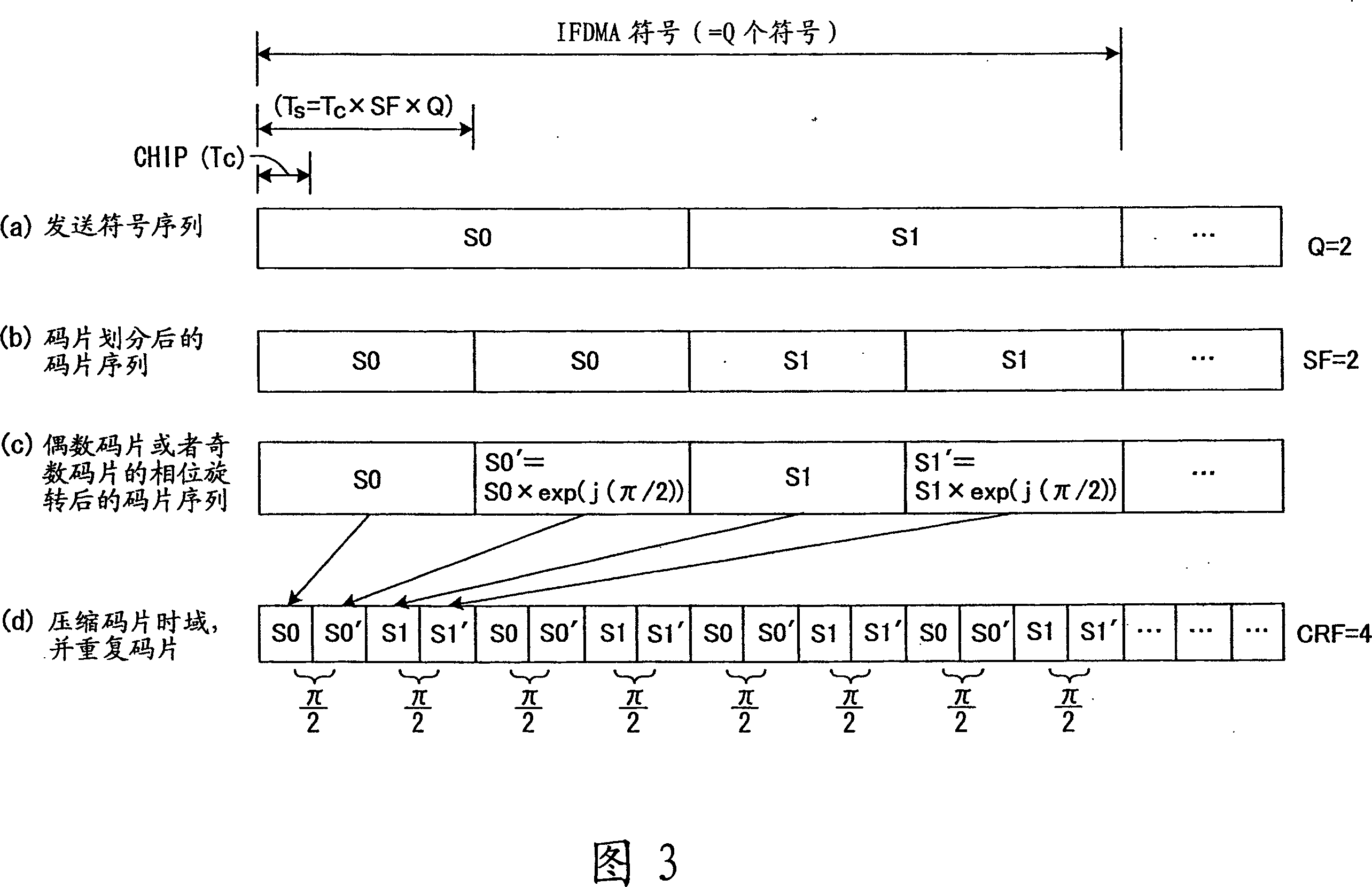
[0105] The channel encoder 11 performs channel encoding by applying error correction encoding such as turbo encoding or convolutional encoding to the input binary information sequence, and the data modulation unit 12 converts the channel-encoded data sequence into I, Q complex number components in QPSK, for example (symbol). As shown in (a) of FIG. 3 , one IFDMA symbol consists of Q (Q=2 in the figure) symbols S0 and S1.

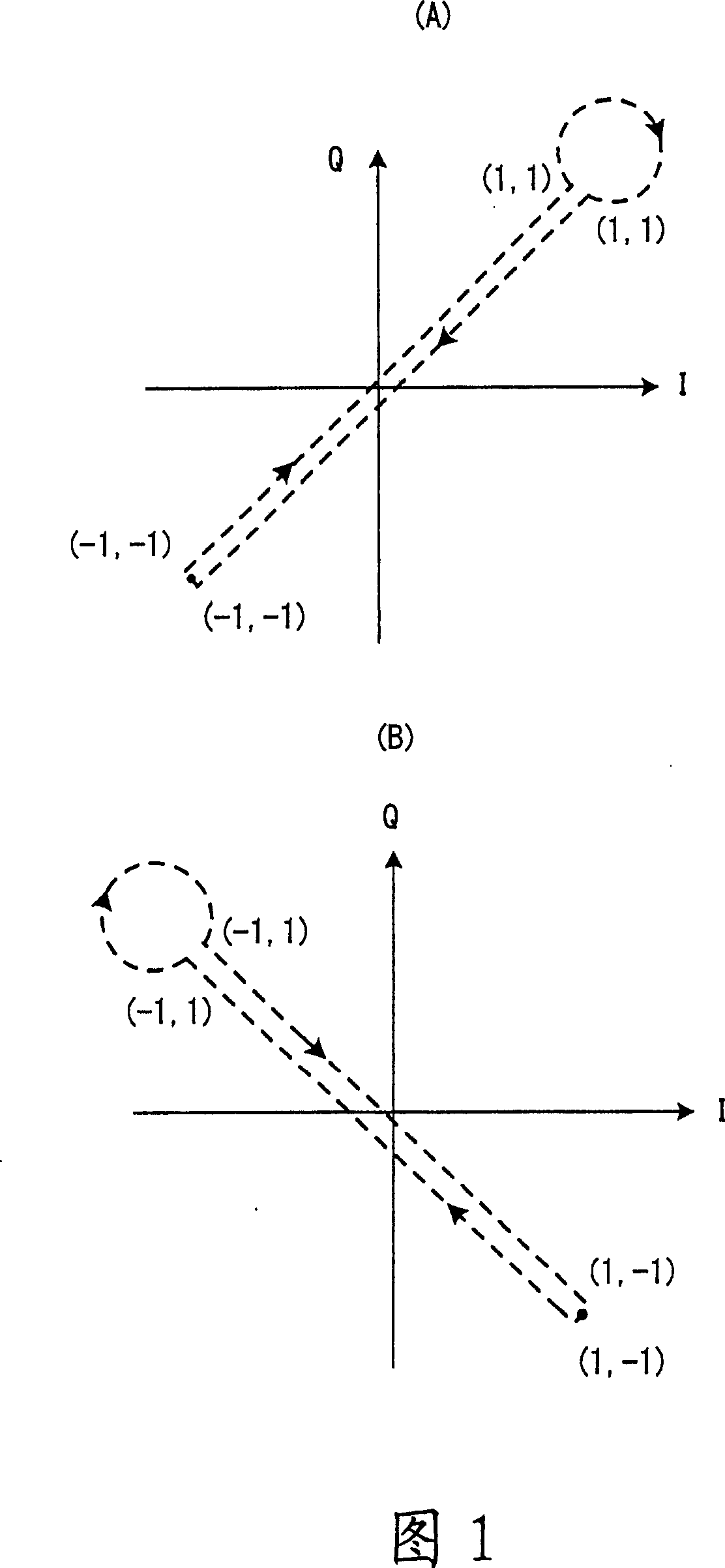
[0106] The chip division unit 13 divides each symbol of the transmitted symbol sequence into SF (in the figure, SF=2) chips (see (b) of FIG. 3 ), and the π / 2 phase rotation unit 14 pairs divid...

no. 2 example

[0113] In a first embodiment, the phase of the even or odd chips in the chip sequence is rotated by π / 2 or -π / 2 in order to reduce the PAPR. In the first embodiment, however, the phase rotation unit 16 also performs a frequency shift specific to the mobile station. Therefore, depending on the frequency dedicated to the mobile station, there are cases where the PAPR cannot be reduced. FIG. 4 is a diagram explaining operations in these cases, and (a) to (d) of FIG. 4 correspond to (a) to (d) of FIG. 3 when Q=1, SF=2, and CRF=4.

[0114] The amount of phase rotation θ performed for each symbol of the repeating chip sequence (see (d) of FIG. 4 ) is given by formula (6). When Q=1, SF=2, CRF=4, and k=2, the phase rotation unit 16 performs phase rotation that increases sequentially in increments of π / 2 for each chip. As a result, the phase rotation amount of each chip becomes as shown in (e) and (f) of FIG. 4 , and the frequency spectrum becomes as shown in (h) of FIG. 4 .

[0115...

no. 3 example

[0144] Fig. 11 is a block diagram of the frequency division multiplexing transmission device of the third embodiment of the present invention, and Fig. 12 is a figure explaining the operation of this frequency division multiplexing transmission device, wherein in Fig. 11, the first implementation shown in Fig. 2 Like parts of the examples are given the same reference numerals.

[0145] This third embodiment differs from the first embodiment in that it compresses the time domain of each symbol of the transmission sequence, then repeats these symbols a specified number of times (CRF times), and rearranges the obtained repeated symbol sequence symbols, making the permutation the same as that of the transmitted symbol sequence, after which chip division and π / 2 phase rotation are performed; the operations of other parts are the same.

[0146] The channel encoder 11 performs channel encoding by performing error correction encoding such as turbo encoding or convolutional encoding on...


PUM


Abstract

In a frequency-division multiplexing transmission apparatus for transmitting data in a frequency spectrum specific to a mobile station, a chip-dividing unit divides each symbol of a transmission-symbol sequence into chips; a first phase rotation unit performs pi / 2 phase rotation for the odd-numbered chips of the divided chips; a chip-repetition and rearrangement unit compresses the time domains of each chip of the chip sequence after phase rotation, then repeats the chips a specified number of times and rearranges the chips of the obtained repetitive-chip sequences so that they have the same arrangement as the original chip sequence; a second phase rotation unit performs phase rotation that changes at a speed specific to a mobile station for each chip of the rearranged repeti tive-chip sequence; and a transmission unit transmits said phase-rotated chips.

Description

technical field [0001] The present invention relates to a frequency division multiplexing transceiver apparatus and method for transmitting and receiving data through a mobile-station-specific frequency spectrum, and more particularly to a frequency-division multiplexing method for transmitting symbols after undergoing a phase rotation changing at a mobile-station-specific speed Multiplexing transceiver device and method thereof. Background technique [0002] DS-CDMA (Direct Sequence Code Division Multiple Access) multiplies a narrowband transmission signal with a spreading code to spread and transmit the transmission signal over a wider frequency band. In DS-CDMA, when each of a plurality of mobile stations transmits a transmission signal after multiplying it by a spreading code having a specific spreading factor SF, the information transmission speed becomes 1 / SF. Therefore, in order to realize frequency utilization efficiency equivalent to TDMA, it is necessary to accomm...

Claims


Application Information

Patent Timeline
Patent Type & Authority Applications(China)
IPC IPC(8): H04B7/26H04B1/707H04J1/00H04J11/00H04L27/01
CPCH04B1/692H04B1/7097H04B2201/70706
Inventor 川崎敏雄
Owner FUJITSU LTD
Why Eureka
Try Eureka