External resonator and semiconductor laser module using the same

An external resonator, laser module technology, applied in the structure/shape of semiconductor lasers, semiconductor laser optical devices, optical resonators, etc., can solve the problems of wide installation space, increase in the number of parts, high price, etc., and achieve the reduction of the number of parts, Reduced installation space and excellent spectral characteristics

Inactive Publication Date: 2005-09-28
KYOCERA CORP
View PDF0 Cites 4 Cited by
  • Summary
  • Abstract
  • Description
  • Claims
  • Application Information

AI Technical Summary

Problems solved by technology

However, in this case, it is necessary to prepare an expensive series-type optical isolator 18 and install it separately. Therefore, the number of parts increases and a wide installation space is required.

Method used


Image

  • External resonator and semiconductor laser module using the same
  • External resonator and semiconductor laser module using the same
  • External resonator and semiconductor laser module using the same

Examples


Embodiment

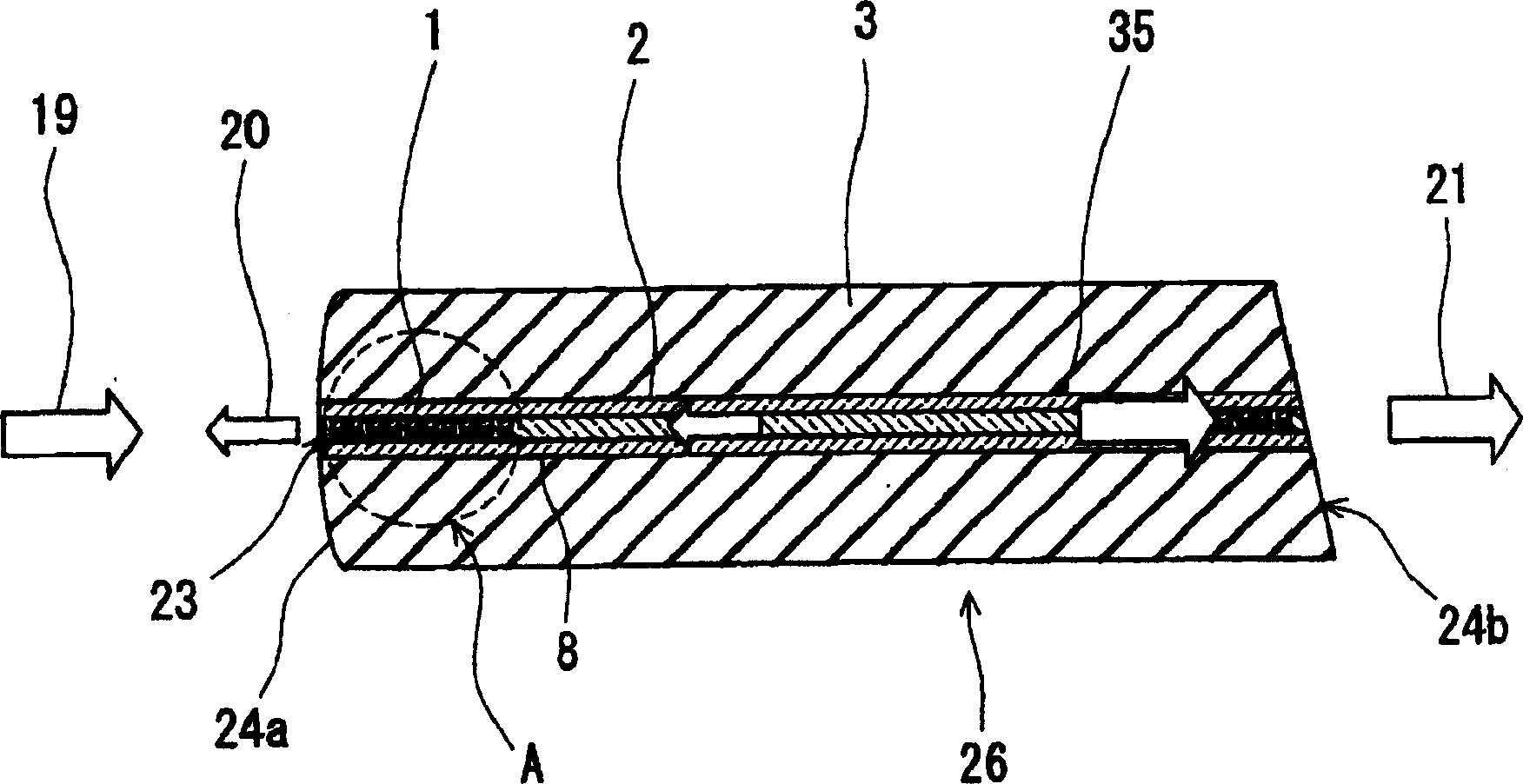
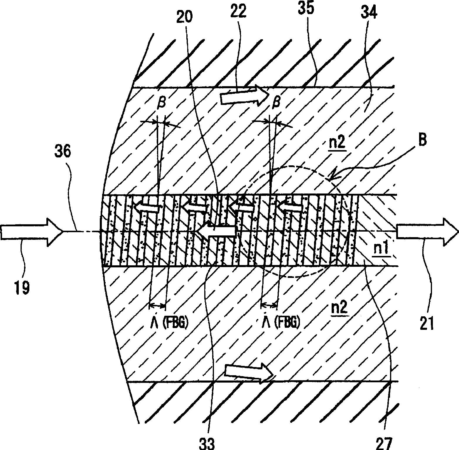
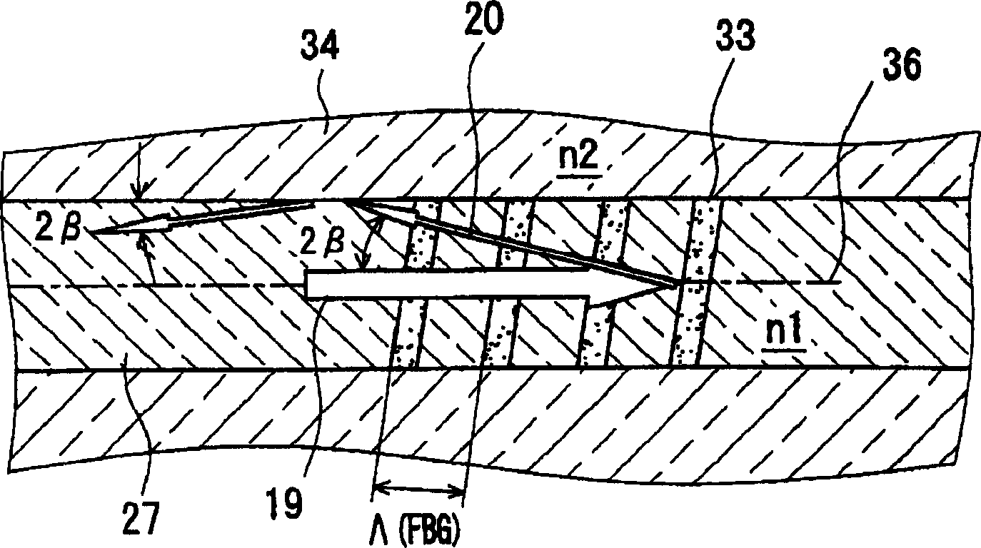
[0090] actually fabricate the external resonator according to the invention and install it in Figure 7 shown in the semiconductor laser module. Using the mode effective refractive index n 1 =1.525, n 2 =1.51, Δ=0.00979, the phase mask 17 of the optical fiber 2 of θc=8° and Λ (MASK)=951 (nm), make reflected light central wavelength λ B FBG1 at 1450nm. Here, Δ and θ c It can be calculated by the following formula.

[0091] Δ=(1.525 2 -1.51 2 ) / (2×1.525 2 ) = 0.00979

[0092] θ c = sin -1 (2×0.00979) 1 / 2 =8.04°

[0093] The intensity of the UV light irradiated to the phase mask 17 is about 500 mW. In addition, the intensity distribution of UV light has a Gaussian shape, and the magnitude of the amount of change in the refractive index of FBG1 has a Gaussian shape distribution in the central axis direction of FBG1. And, at the time of recording, the optical fiber is tilted by the inclination angle β from the horizontal. Here, the inclination angle β=3° (0°c / 2).

...


PUM

PropertyMeasurementUnit
wavelengthaaaaaaaaaa
thicknessaaaaaaaaaa
refractive indexaaaaaaaaaa

Abstract

An external resonator is provided with a fiber having a fiber Bragg grating for reflecting light of a specific wavelength and a ferrule which holds the above described fiber inside thereof. At least some phase gratings from among the respective phase gratings that form fiber Bragg grating are inclined relativ e to the optical axis of the fiber.

Description

technical field [0001] The present invention relates to an optical fiber including a fiber Bragg grating, an external resonator using the optical fiber, and a semiconductor laser module using the external resonator. Background technique [0002] It is desired that not only the output power but also the wavelength of the semiconductor laser that outputs laser light be stable under the environmental conditions of use. A Fabry-Perot type semiconductor laser is reflected between the end faces of a substrate with a laser element length of 500 μm or less to perform multi-mode oscillation. Therefore, its spectral characteristics become broad. In addition, due to thermal expansion of the material of the semiconductor laser element, there is also a change in the refractive index of the active region, so that the length of the resonator between the end faces changes, and the wavelength of the oscillating laser light changes. In order to suppress these, if a fiber Bragg grating (here...

Claims


Application Information

Patent Timeline
Patent Type & Authority Applications(China)
IPC IPC(8): G02B5/26G02B6/02G02B6/34G02B6/42G02F1/025H01S3/08H01S5/00H01S5/022H01S5/024H01S5/026H01S5/10H01S5/125H01S5/14
CPCH01S5/02438H01S5/02216H01S5/02284G02B6/4203G02B6/02085H01S5/0064H01S5/02415G02B6/4206H01S5/141H01S5/005G02B6/29319G02B6/02138H01S5/146H01S5/02251
Inventor 奥田通孝重冈义之
Owner KYOCERA CORP
Why Eureka
Try Eureka