Locus generation apparatus, control method for locus generation apparatus, and storage medium

A trajectory generation and trajectory technology, applied in the direction of torque/mechanical power control, program control, digital control, etc., can solve the problems of unable to handle heavy goods, not increasing the motor, shortening the driving time, etc., and achieve peak suppression , The effect of increasing the handling weight and shortening the handling time

Inactive Publication Date: 2018-04-10
ORMON CORP
View PDF12 Cites 3 Cited by
  • Summary
  • Abstract
  • Description
  • Claims
  • Application Information

AI Technical Summary

Problems solved by technology

In addition, in Patent Document 2, although the speed mode of the pulse motor is designed, it is not necessarily the best
[0010] Therefore, in the methods described in Patent Documents 1 and 2, heavy loads cannot be transported and the driving time can be shortened without increasing the capacity of the motor.

Method used


Image

  • Locus generation apparatus, control method for locus generation apparatus, and storage medium
  • Locus generation apparatus, control method for locus generation apparatus, and storage medium
  • Locus generation apparatus, control method for locus generation apparatus, and storage medium

Examples


Embodiment approach 1

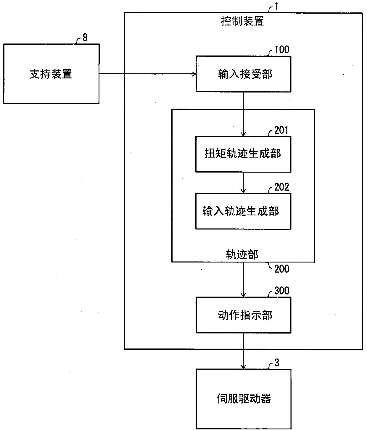
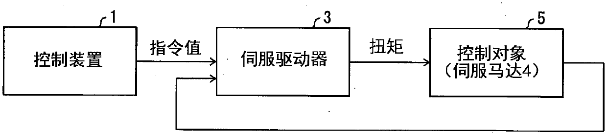
[0071] Hereinafter, embodiments of the present invention will be described in detail. The control system of this embodiment is a system in which the control device (and figure 2 The control object (corresponding to the control device 1 in the etc.) is generated in the figure 2 Corresponding to the control object 5 in etc.) at the target time (terminal time) to move to the input trajectory of the target position (specified position, terminal position), and input to the servo driver (with figure 2 Corresponding to the servo driver 3 in etc.), drive the servo motor (with figure 2 Corresponding to the servo motor 4 in etc.) to move the controlled object.

[0072] In addition, the input trajectory generated in the control device can control the peak torque. Furthermore, by controlling the peak value of the torque, if the drive device is the same as the drive device corresponding to the peak value in the conventional structure, the conveyance weight can be increased compared ...

Embodiment approach 2

[0114] based on Figure 7 , Figure 8 Other embodiments of the present invention will be described in detail as follows. In addition, for convenience of description, the same reference numerals are attached to components having the same functions as those described in the above-mentioned embodiments, and their descriptions are omitted.

[0115] [summary]

[0116] In Embodiment 1, the torque trajectory is obtained by setting the torque value and switching time as the input trajectory. However, in an actual device, due to the occurrence of model errors, the controlled object may not reach the terminal position and not reach the terminal speed at the terminal time even if the control is performed with a torque that conforms to the command.

[0117] Specifically, refer to Figure 7 Be explained. Figure 7 It is a diagram showing the relationship between the torque trajectory, the actual position of the control object, and time when the torque trajectory is used as the input t...

Embodiment approach 3

[0127] based on Figure 9 ~ Figure 14 Other embodiments of the present invention will be described in detail as follows. In addition, for convenience of description, components having the same functions as those described in the above-described embodiments are assigned the same reference numerals, and descriptions thereof are omitted.


PUM


Abstract

The present invention provides a locus generation device that can suppress the peak torque without greatly changing the structure of the device. An apparatus includes an input reception unit (100) forreceiving a designated driving time, and a locus unit (200) that generates a torque locus with a maximum value at its minimum by adjusting a switching timing and a maximum value under the conditionsthat the torque locus is a rectangular wave, the absolute values of the maximum value and the minimum value of torque are equal, and switching between the maximum value and the minimum value of the torque occurs once.

Description

technical field [0001] The present invention relates to a trajectory generating device and the like for generating an input trajectory input to a control device. Background technique [0002] In the control of the operation of machinery and equipment, when conveying heavy goods or shortening the driving time, it is necessary to increase the driving speed of the driving unit, increase the torque value applied to the driving unit, and other controls. However, even if the torque value to be applied is increased, it is meaningless if the capacity of the corresponding drive unit (motor) does not correspond to it. Therefore, in the case of conveying a heavy load or when the torque becomes overloaded when the driving time is shortened, it is necessary to increase the capacity of the motor. [0003] However, increasing the capacity of the motor has disadvantages such as an increase in the size of the power supply equipment and an increase in power consumption. In addition, in many...

Claims


Application Information

Patent Timeline
Patent Type & Authority Applications(China)
IPC IPC(8): G05D17/02
CPCG05D17/02G05B19/416G05B2219/43034G05B2219/43045G05B2219/43092G05B19/371G05B19/4141G05B2219/34013G05B2219/41
Inventor 古贺达也
Owner ORMON CORP
Why Eureka
Try Eureka