Fuel cell system and method therefor

a fuel cell and system technology, applied in the direction of secondary cells, cell components, electrochemical generators, etc., can solve the problems of sudden voltage drop, increase of surplus power, and non-consideration of conventional techniques for fuel cell voltage decreasing speed, so as to prevent the electric storage device from being overcharged, increase the voltage reduction speed, and restrain the sudden generation of surplus power

Active Publication Date: 2011-12-27
TOYOTA JIDOSHA KK
View PDF11 Cites 4 Cited by
  • Summary
  • Abstract
  • Description
  • Claims
  • Application Information

AI Technical Summary

Benefits of technology

[0008]With this arrangement, when the catalyst activation process is carried out, the controller calculates a receiving capability (e.g., the power which can be charged into an electric storage device and / or power which can be consumed by a load), and controls the output voltage changing speed of the fuel cell for the catalyst activation process according to the receiving capability, thus restraining the occurrence of surplus power which may adversely affect a receiving device.
[0020]With this arrangement, when the catalyst activation process is carried out, as the receivable power calculated by the power calculating means is smaller, that is, as the receivable power of at least one of the electric storage device and a load of the fuel cell, which will be an object receiving surplus power generated by the fuel cell, is smaller, the output voltage changing speed of the fuel cell is limited so as to restrain sudden generation of surplus power caused by a reduction in the output voltage of the fuel cell. Thus, even if the receivable power of at least one of the load of the fuel cell and the electric storage device becomes small, surplus power is gradually generated as the output voltage changing speed of the fuel cell decreases and surplus power will not exceed the receiving capability (the receivable power) of the load of the fuel cell or the electric storage device. This makes it possible to restrain a peak value of surplus power from increasing, adversely affecting the load of the fuel cell or the electric storage device. Further, when the surplus power generated by the fuel cell is charged into the electric storage device as the output voltage of the fuel cell decreases, the output voltage changing speed of the fuel cell is limited within the range in which the passing power which passes through the voltage converter does not exceed the upper limit (permissible value) of the voltage converter, thus making it possible to protect the voltage converter from influences (such as heat) caused by surplus power passing therethrough.

Problems solved by technology

However, the conventional technique does not give consideration to determining the voltage decreasing speed of a fuel cell while giving consideration to surplus power of the fuel cell when carrying out the catalyst activation process of the fuel cell.
Hence, there have been cases where an inconvenience results when activating a catalyst layer of the fuel cell.
For example, increasing the fuel cell voltage reduction speed in order to finish the catalyst activation process in shorter time causes a sudden voltage drop in a state wherein there is a plenty of a residual gas (oxygen).
Hence, the amount of surplus power increases and excessive power is supplied accordingly.
As a result, there has been a danger of causing deteriorated performance, such as deteriorated durability, of a load of the fuel cell or a battery (electric storage device).

Method used


Image

  • Fuel cell system and method therefor
  • Fuel cell system and method therefor
  • Fuel cell system and method therefor

Examples


Embodiment Construction

[0028]The following will describe a fuel cell system in accordance with an embodiment of the present invention with reference to the accompanying drawings. In the present embodiment, the description will be given to an example wherein the present invention has been applied to a vehicle-mounted power generation system of a fuel cell vehicle.

(Explanation of Configuration)

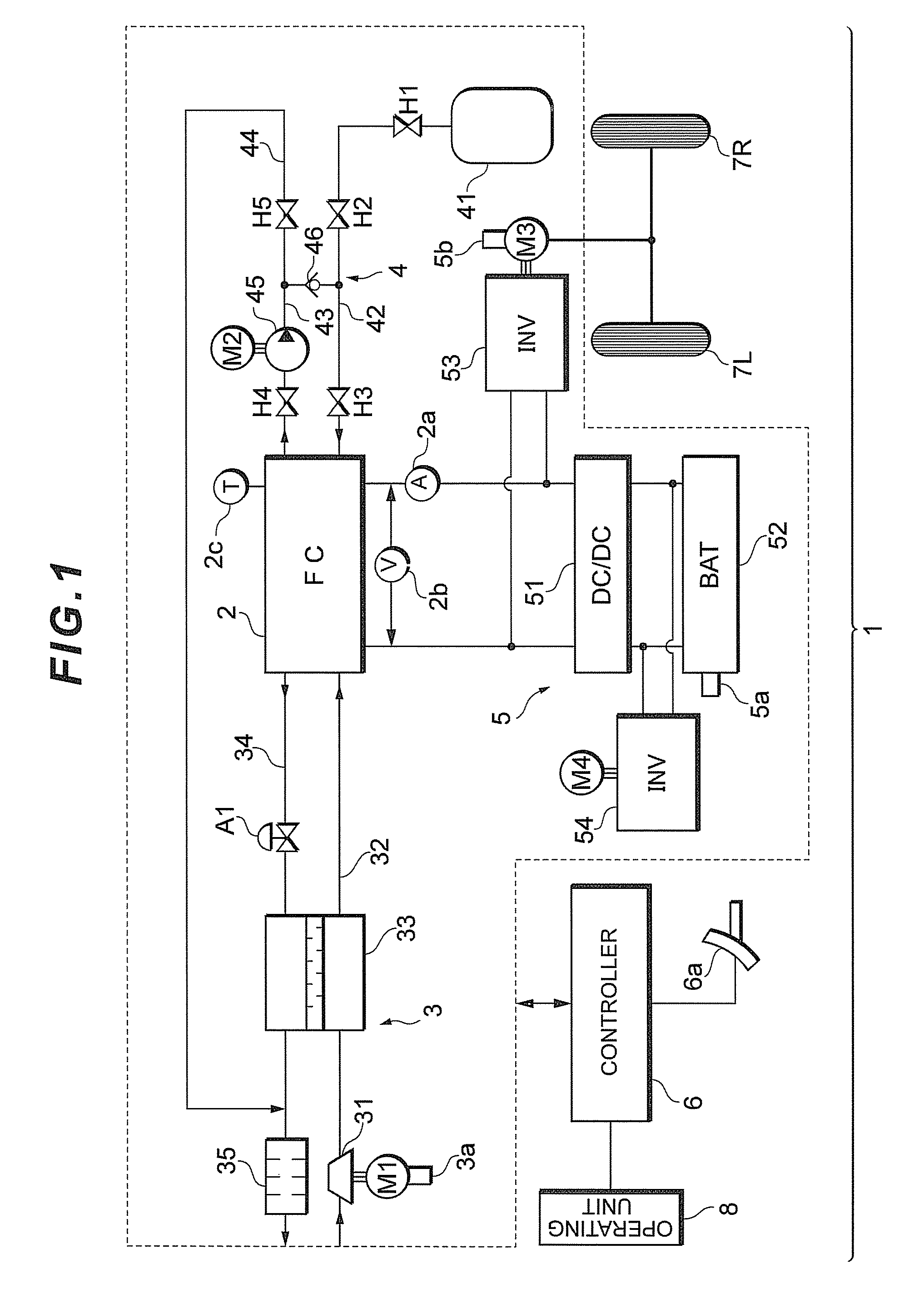
[0029]First, by referring to FIG. 1, the configuration of a fuel cell system 1 in accordance with the embodiment of the present invention will be described.

[0030]As illustrated in FIG. 1, the fuel cell system 1 according to the present embodiment is equipped primarily with a fuel cell 2 which carries out power generation by receiving supplied reactant gases (an oxidizing gas and a fuel gas) and generates power by the power generation, an oxidizing gas piping system 3 which supplies air as the oxidizing gas to the fuel cell 2, a fuel gas piping system 4 which supplies a hydrogen gas as the fuel gas to the fuel cell 2, ...


PUM

PropertyMeasurementUnit
output voltageaaaaaaaaaa
timeaaaaaaaaaa
receivable poweraaaaaaaaaa

Abstract

When an output voltage of a fuel cell is lowered to carry out a catalyst activation process so as to activate a catalyst during an intermittent operation of the fuel cell, if generated power P1 exceeds allowed battery charge power, while generated power P2 does not exceed the allowed battery charge power, then low speed corresponding to the generated power P2 is selected and the output voltage of the fuel cell is decreased toward a target voltage on the basis of the low speed, which has been selected, thereby restraining sudden generation of surplus power caused by a reduction in the output voltage of the fuel cell. By the control described above, a voltage reduction speed of a fuel cell is determined according to a receiving capability of an object which receives surplus power generated by the fuel cell during the catalyst activation process of the fuel cell.

Description

[0001]This is a 371 national phase application of PCT / JP2008 / 054675 filed 7 Mar. 2008, which claims priority to Japanese Patent Application No. 2007-057572 filed 7 Mar. 2007, the contents of which are incorporated herein by reference.TECHNICAL FIELD[0002]The present invention relates to a fuel cell system and more particularly to a fuel cell system capable of decreasing an output voltage of a fuel cell when carrying out a catalyst activation process.BACKGROUND ART[0003]Hitherto, in a fuel cell system, adsorption of oxygen into a catalyst layer of a fuel cell in operation causes a drop in an output voltage of the fuel cell. In such a case, a process for activating the catalyst layer of a fuel cell stack (i.e., reduction process) is carried out by interrupting the supply of oxygen to the fuel cell and decreasing the power generation voltage of the fuel cell down to a reduced zone of the catalyst layer.[0004]As a technique related to such a catalyst activation process of a fuel cell, t...

Claims


Application Information

Patent Timeline
Patent Type & Authority Patents(United States)
IPC IPC(8): H01M16/00
CPCH01M8/04238H01M8/04365H01M8/04373H01M8/04559H01M8/04626H01M8/04679H01M8/04865H01M16/006H01M8/04589Y02E60/50Y02E60/10
Inventor UMAYAHARA, KENJIYOSHIDA, MICHIO
Owner TOYOTA JIDOSHA KK
Why Eureka
Try Eureka