Terminal signal transmit-receive device and method

A terminal signal and signal transceiving technology, which is applied in the field of communication, can solve the problems of poor radiation power and receiving sensitivity of mobile phones, large screens, etc., and achieve the effect of improving the performance of transceiving

Inactive Publication Date: 2016-10-05
ZTE CORP
View PDF4 Cites 5 Cited by
  • Summary
  • Abstract
  • Description
  • Claims
  • Application Information

AI Technical Summary

Problems solved by technology

However, as the terminal electronic products support more and more functional frequency bands, the appearance is getting thinner and the screen is getting bigger and bigger, and they are on the road to ultra-thin and ultra-large screens, how to improve the receiving and transmitting performance of the terminal electronic products is a constant challenge. question of inquiry
[0003] Taking the mobile phone as an example, at present, by measuring the reception and emission indicators of the mobile phone in a special mode, it can objectively reflect the performance indicators of the mobile phone’s reception and transmission in actual use. Due to the limitation of the shape of the mobile phone, the built-in antenna of the mobile phone mostly uses the flexible circuit board FPC (Flexible Printed Circuit board) and laser antenna LDS (Laser Direct Structuring), and the antenna position is mostly at the bottom of the mobile phone. Usually, when the antenna is at the bottom of the mobile phone, the radiation power and receiving sensitivity of the mobile phone will be found when the head-hand mode test is performed. OTA (Over The Air) performance becomes very poor due to hand model coverage

Method used


Image

  • Terminal signal transmit-receive device and method
  • Terminal signal transmit-receive device and method
  • Terminal signal transmit-receive device and method

Examples


Embodiment Construction

[0024] In order to facilitate the understanding of those skilled in the art, the embodiments of the present invention will be further described below in conjunction with the accompanying drawings, which cannot be used to limit the protection scope of the present invention. It should be noted that, in the case of no conflict, the embodiments in the present application and various manners in the embodiments can be combined with each other.

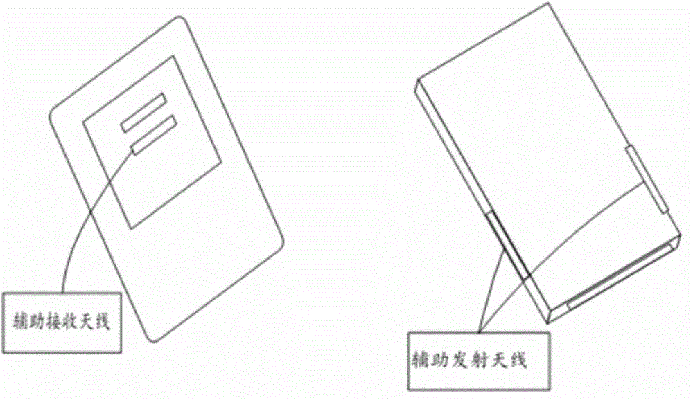
[0025] figure 1 It is a schematic diagram of the position of the auxiliary antenna of the terminal signal transceiving device according to the embodiment of the present invention, as shown in figure 1 As shown, in the embodiment of the present invention, the auxiliary antenna includes an auxiliary receiving antenna and an auxiliary transmitting antenna, wherein the auxiliary receiving antenna is arranged on the upper part of the rear case of the terminal, and the auxiliary transmitting antenna is arranged on the side of the terminal. In a t...


PUM


Abstract

The present invention provides a terminal signal transmit-receive device. The device comprises a master antenna and an auxiliary antenna which are used for transmitting and receiving radio frequency signals, a master antenna matching circuit and an auxiliary antenna matching circuit which are respectively connected with the master antenna and the auxiliary antenna, a combiner configured to overlap the signals received by the master antenna and the auxiliary antenna and a power divider configured to distribute signals emitted by the terminals and send the signals to the master antenna and the auxiliary antenna. The auxiliary antenna can effectively improve the transmit-receive performance of signals of a terminal.

Description

technical field [0001] The present invention relates to the technical field of communications, in particular to a terminal signal transceiving device and a signal transceiving method. Background technique [0002] With the rapid development of science and technology today, terminal electronic products, etc., as people's must-haves in today's life, support more and more frequency band functions. However, as terminal electronic products support more and more functional frequency bands, their shapes are getting thinner and their screens are getting bigger and bigger, and they are on the road to ultra-thin and ultra-large screens, how to improve the receiving and transmitting performance of terminal electronic products is always a challenge. question of inquiry. [0003] Taking the mobile phone as an example, at present, by measuring the reception and emission indicators of the mobile phone in a special mode, it can objectively and practically reflect the performance indicators...

Claims


Application Information

Patent Timeline
Patent Type & Authority Applications(China)
IPC IPC(8): H04B1/38
CPCH04B1/38
Inventor 秦波
Owner ZTE CORP
Why Eureka
Try Eureka