Check patentability & draft patents in minutes with Patsnap Eureka AI!

Special punching machine

A technology of punching and special machines, applied in metal processing, etc., can solve problems such as low efficiency and cumbersome processes, and achieve the effects of improving production efficiency, reducing process steps, and ingenious overall structure

Active Publication Date: 2016-10-12
昆山三众汽车部件制造有限公司
View PDF5 Cites 1 Cited by
  • Summary
  • Abstract
  • Description
  • Claims
  • Application Information

AI Technical Summary

Problems solved by technology

[0002] In the process of manufacturing automobile bumpers, both ends of the product need to be punched, and the top surface is a large hole, and the bottom surface is a small hole. When the current equipment performs the above-mentioned process operations, it is necessary to punch out the large holes. Take off the workpiece, turn it over and put it into the equipment to punch small holes. This method is cumbersome and inefficient.

Method used


Image

  • Special punching machine
  • Special punching machine
  • Special punching machine

Examples


Embodiment Construction

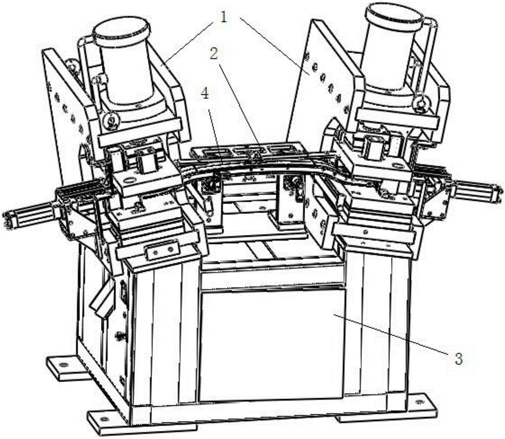
[0019] see Figure 1 to Figure 7 , a special punching machine, including a machine platform 3, a locking mechanism 2 located on the machine platform, two punching mechanisms 1, and the two punching mechanisms 1 are symmetrically arranged on both sides of the locking mechanism 2, and the product 4 The two ends are located in the two punching mechanisms 1 respectively, and the middle part of the product 4 is located in the locking mechanism 2 .

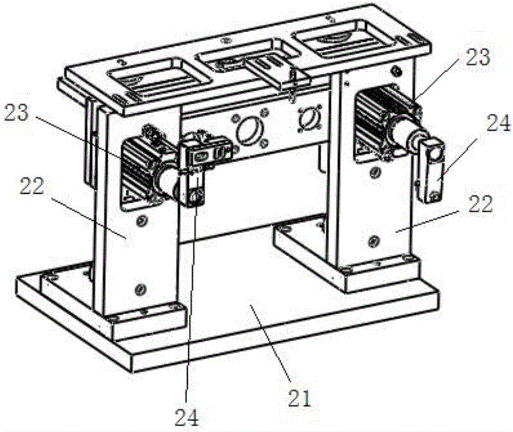
[0020] The locking mechanism 2 includes a base plate 21 installed on the machine platform, and two parallel vertical plates 22 located on the base plate 21. A rotary cylinder 23 is arranged on the two vertical plates, and a locking block is provided at the end of the rotary cylinder 23. 24. The rotating cylinder 23 drives the locking block 24 to rotate to complete the locking of the product.

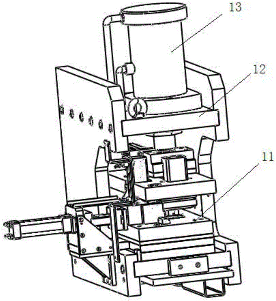
[0021] The punching mechanism 1 includes a mounting frame 12, a driver 13 positioned on the mounting frame 12, and a punching die 11. The driver...


PUM


Abstract

The invention discloses a special punching machine comprising a machine table, a locking mechanism located on the machine table, and two punching mechanisms. Each punching mechanism comprises an installing frame, a driving piece and a punching die, wherein the driving piece and the punching die are located on the installing frame. Each punching die comprises a material supporting assembly, an adjustable punch assembly located and a waste material discharging cylinder, wherein the adjustable punch assembly and the waste material discharging cylinder are located above the material supporting assembly. Each adjustable punch assembly comprises a large punching mandrel pressing block, a fixing plate located below the large punching mandrel pressing block, a large punching mandrel installing plate installed on the bottom face of the fixing plate, and a large punching mandrel installed in the large punching mandrel installing plate, wherein an adjusting plate cylinder is further arranged on the fixing plate and connected with an adjusting plate; a small punching mandrel pressing block is further arranged at the bottom of the large punching mandrel pressing block; a small punching mandrel installing plate is further arranged on the top face of the large punching mandrel installing plate and internally provided with a small punching mandrel; and the small punching mandrel is located in the large punching mandrel. The special punching machine is ingenious in integrated structure, process steps are reduced, and the production efficiency is improved.

Description

technical field [0001] The invention relates to the field of automobile parts manufacturing, in particular to a special punching machine. Background technique [0002] In the process of manufacturing automobile bumpers, both ends of the product need to be punched, and the top surface is a large hole, and the bottom surface is a small hole. When the current equipment performs the above-mentioned process operations, it is necessary to punch out the large holes. Remove the workpiece, turn it over and put it into the equipment to punch small holes. This method is cumbersome and inefficient. Contents of the invention [0003] The purpose of the present invention is to provide a special punching machine with high efficiency. [0004] The present invention achieves the above object through the following technical solutions: a special punching machine, including a machine table, a locking mechanism located on the machine table, and two punching mechanisms, and the punching mechan...

Claims


Application Information

Patent Timeline
IPC IPC(8): B26F1/02B26F1/14B26D7/18B26D7/02
CPCB26D7/02B26D7/18B26F1/02B26F1/14
Inventor 曾明
Owner 昆山三众汽车部件制造有限公司
Features
  • R&D
  • Intellectual Property
  • Life Sciences
  • Materials
  • Tech Scout
  • Unparalleled Data Quality
  • Higher Quality Content
  • 60% Fewer Hallucinations
Learn More