Automatic part taking device after tapping

An automatic pick-up and thread-tapping technology, applied in tangent devices, tangential feed devices, metal processing, etc., can solve the problems of low efficiency and mixing materials, and achieve the effects of reduced labor costs, high degree of automation, and ingenious overall structure

Pending Publication Date: 2020-03-24
无锡诺飞高新技术有限公司
0 Cites 0 Cited by

AI-Extracted Technical Summary

Problems solved by technology

However, this working method is not only inefficient, but also prone to artificial mixing, that is, the ...

Method used

In the present embodiment, blanking chute 31 comprises blanking end 311 and discharge end 312, and blanking end 311 is higher than discharge end 312, and discharge end 312 stretches in collecting box 32, can like this After the electromagnet 24 moves to the discharge end 311, the power-off loses the adsorption force, and the parts fall and slide from the discharge end 311 to the discharge end 312, and finally fall into the collection box 32, and the discharge end 312 stretches out. Entering into the collection box 32 can prevent parts from falling out and being damaged.
Tapping mechanism 1 comprises tapping machine 11 and turntable 12, and turntable 12 is arranged on the below of tapping mechanism 11, and turntable 12 is evenly provided with several groups of pa...

Abstract

The invention relates to the technical field of tapping machine equipment, in particular to an automatic part taking device after tapping. The device comprises a tapping mechanism, a part taking mechanism and a discharging mechanism. The tapping mechanism, the part aking mechanism and the discharging mechanism are independent of one another. The tapping mechanism comprises a tapping machine and aturntable; the turntable is arranged below the tapping machine; and a plurality of groups of part placing parts are uniformly arranged on the turntable. The part taking mechanism comprises a rack, a rotatable and telescopic first movable arm is horizontally arranged on the rack, a liftable second movable arm is vertically arranged on the first movable arm and an electromagnet is arranged on the second movable arm. The discharging mechanism comprises a discharging sliding way and a material collecting box. The discharging sliding way is obliquely arranged and guided into the material collectionbox. The device is ingenious in overall structure, reasonable in design and capable of achieving full-automatic operation, workers only need to feed materials to the rotary disc, the automation degree is high, the working efficiency and the box filling efficiency are greatly improved, the labor cost is reduced and the material mixing phenomenon caused by human factors is eliminated.

Application Domain

Thread cutting feeding devicesMetal working apparatus

Technology Topic

Manufacturing engineeringAutonomation +4

Image

  • Automatic part taking device after tapping
  • Automatic part taking device after tapping

Examples

  • Experimental program(1)

Example Embodiment

[0018] The preferred embodiments of the present invention will be described below with reference to the accompanying drawings. It should be understood that the preferred embodiments described herein are only used to illustrate and explain the present invention, but not to limit the present invention.
[0019] like figure 1 , 2 As shown, the present invention is an automatic device for picking up parts after tapping, including a tapping mechanism 1, a picking mechanism 2 and a blanking mechanism 3, and the tapping mechanism 1, the picking mechanism 2 and the blanking mechanism 3 are independent of each other , as the name implies, the tapping mechanism 1 is used for tapping the parts, the pick-up mechanism 2 is used to take out the parts processed at the tapping mechanism 1, and the blanking mechanism 3 is used to collect and store the picked-up mechanism 2 removed parts.
[0020] The tapping mechanism 1 includes a tapping machine 11 and a turntable 12, the turntable 12 is arranged below the tapping mechanism 11, and several groups of parts placement parts 13 are evenly arranged on the turntable 12, so that the staff can first place the parts to be processed. After being placed on the parts placement part 13, the turntable 12 is rotated to rotate the parts placement part 13 to a suitable position, and then the tapping machine 11 taps the parts on the parts placement part 13. During the processing, the staff The next group of parts can be placed on another group of parts placement portion 13, which simplifies the operation steps, saves work time, and improves work efficiency. Then the tapping machine 11 ends its work, and the turntable 12 continues to rotate, so that the next group of parts to be processed rotates to a proper position, and the previous group of parts that have been tapped rotates to a position where the pick-up mechanism 2 can take out.
[0021] The pick-up mechanism 2 includes a frame 21. The frame 21 is provided with a rotatable and retractable first movable arm 22 horizontally. The first movable arm 22 is vertically provided with a liftable second movable arm 23. The arm 23 is provided with an electromagnet 24, and the number and position of the electromagnet 24 are matched with the parts placement portion 13, so that the electromagnet 24 can be rotated and moved to the place by the first movable arm 22 that is rotatable and retractable. Directly above the part placement part 13 of the processed parts, the electromagnet 24 can be lowered by the second movable arm 23 that can be raised and lowered, and then the electromagnet 24 can be energized so that the parts can be adsorbed, and then It rises, rotates and moves to the unloading mechanism 3, the electromagnet 24 loses its magnetic force when the electromagnet 24 is powered off, and the parts fall to the unloading mechanism 3 to realize transfer and collection.
[0022] The unloading mechanism 3 includes the unloading chute 31 and the collecting box 32. The unloading chute 31 is located directly below the pick-up mechanism 2. The unloading chute 31 is inclined and guided into the collecting box 32, so that the parts can be placed in the collecting box 32. When the electromagnet 24 is powered off and loses its magnetic force, it can fall into the unloading chute 31 and then fall into the collecting box 32 for collection.
[0023] In this embodiment, there are three sets of parts placement parts 13, and the included angle between the three sets of parts placement parts 13 is 120°, which can ensure that at least three sets of parts are continuously processed continuously, and its processing efficiency High, and the interval between 120° is set so that neither the pick-up mechanism 2 nor the feeding work of the staff will have any influence on the thread tapping process, and the stability is high.
[0024] In this embodiment, the frame 21 is also provided with an electric control box 25, and the electric control box 25 is electrically connected with the first movable arm 22, the second movable arm 23, the turntable 12 and the electromagnet 24, so that the electric The control box 25 can control the rotation and movement angle and distance of the first movable arm 22 , the lifting distance of the second movable arm 23 , the rotation angle of the turntable 12 and the power-on and power-off of the electromagnet 24 .
[0025] In this embodiment, the first movable arm 22 includes a rotating part 221 and a fixed part 222, the second movable arm 23 is arranged on the fixed part 222, and the rotating part 221 and the fixed part 222 are rotatably connected by a rotating shaft 223, and the rotating part 221 The first motor is connected to the transmission, so that the first motor can drive the rotating part 221 to rotate, thereby driving the electromagnet 24 to rotate to a proper position. The frame 21 is also provided with a translation guide rail 26, the second movable arm 23 is slidably arranged on the translation guide rail 26, and the second movable arm 23 is driven and connected with a second motor, so that the second motor can drive the second movable arm 23. The translation guide rail 26 moves up, thereby driving the electromagnet 24 to move to a proper position.
[0026] In this embodiment, the first movable arm 22 is provided with a vertical guide rail 27, the second movable arm 23 is slidably arranged on the vertical guide rail 27, and the second movable arm 23 is connected to a third motor in a driving manner, so that the third The motor can drive the second movable arm 23 to move up and down on the vertical guide rail 27, thereby driving the electromagnet 24 to move to the position where it is in contact with the processed part.
[0027] In this embodiment, the discharging chute 31 includes a discharging end 311 and a discharging end 312, the discharging end 311 is higher than the discharging end 312, and the discharging end 312 extends into the collecting box 32, which can make the electromagnet 24 After moving to the unloading end 311, the power off and losing the adsorption force, the parts fall off and slide from the unloading end 311 to the discharge end 312, and finally fall into the collecting box 32, and the discharge end 312 extends into the collecting end 312. The inside of the bin 32 can prevent the parts from falling out and being damaged.
[0028] To sum up, the working principle of the present invention for automatically picking up parts after tapping is as follows: first place a group of parts to be processed on the parts placing part 13 , then the turntable 12 rotates to rotate the parts placing part 13 To a suitable position, the tapping machine 11 then taps the parts on the part placement part 13. During the processing, the staff can place the next set of parts on another set of parts placement part 13, and then tap the thread. When the machine 11 finishes working, the turntable 12 continues to rotate, so that the next group of parts to be processed rotates to a proper position, and the previous group of parts that have been tapped rotates to a position that can be taken out by the pick-up mechanism 2 . Then the electric control box 25 controls the first movable arm 22 to rotate and move, and then controls the second movable arm 23 to descend so that the electromagnet 24 is connected to the parts that have been tapped. Then control the second movable arm 23 to rise and the first movable arm 22 to rotate and move, so that the electromagnet 24 is located directly above the unloading end 311, and the electromagnet 24 is powered off to lose its magnetic force, and the parts will fall to the unloading slide. On the track 31 and slide down into the collection box 32 for collection. During the process of picking up and unloading, the tapping machine 11 has finished processing the next group of parts, and at the same time, the worker can continue to put the next group of parts on the turntable 12 . The overall structure is ingenious, the design is reasonable, and the whole process is automated. It only needs workers to load the material on the turntable 12. The degree of automation is high, which greatly improves the work efficiency and packing efficiency, reduces labor costs, and eliminates the confusion caused by human factors. material phenomenon.
[0029] Finally, it should be noted that the above descriptions are only preferred examples of the present invention, and are not intended to limit the present invention.
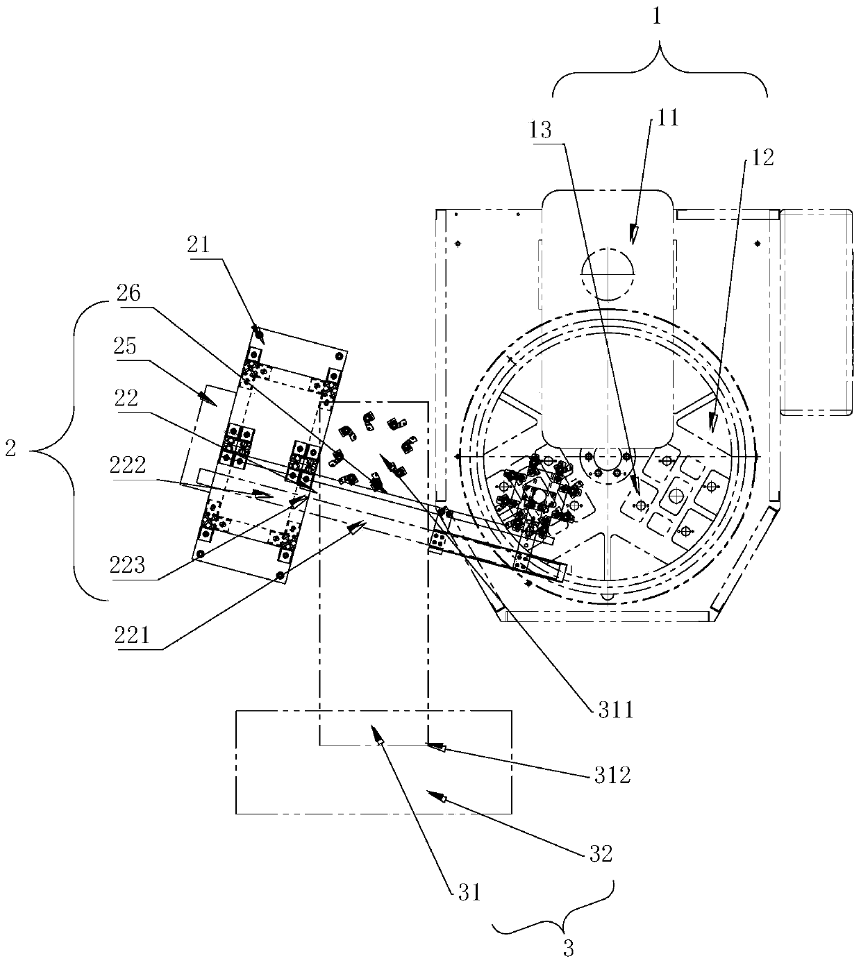
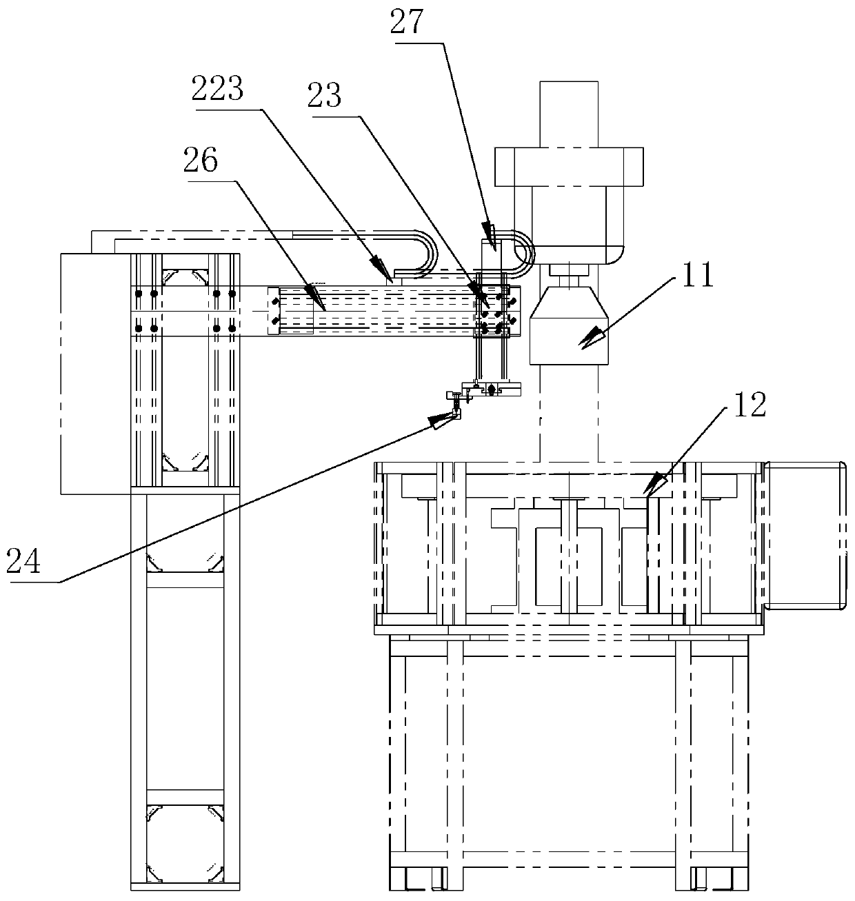
 Although the present invention has been described in detail with reference to the foregoing embodiments, those skilled in the art can still Modifications are made to the technical solutions described in the foregoing embodiments, or equivalent replacements are made to some of the technical features therein. Any modification, equivalent replacement, improvement, etc. made within the spirit and principle of the present invention shall be included within the protection scope of the present invention.

PUM

PropertyMeasurementUnit
Angle120.0deg

Description & Claims & Application Information

We can also present the details of the Description, Claims and Application information to help users get a comprehensive understanding of the technical details of the patent, such as background art, summary of invention, brief description of drawings, description of embodiments, and other original content. On the other hand, users can also determine the specific scope of protection of the technology through the list of claims; as well as understand the changes in the life cycle of the technology with the presentation of the patent timeline. Login to view more.

Similar technology patents

Special punching machine

ActiveCN106003230AThe overall structure is ingeniousReduce process steps
Owner:昆山三众汽车部件制造有限公司

Assembly type fire-fighting emergency lighting lamp

PendingCN111520664AThe overall structure is ingeniousSimple and ingenious
Owner:浙江台谊消防股份有限公司

Medicine storage box automatic medicine taking machine

InactiveCN113892791AThe overall structure is ingeniouscompact structure
Owner:GUANGDONG MECHANICAL & ELECTRICAL COLLEGE

Apple posture fine adjustment device and posture adjustment equipment

PendingCN110562530AThe overall structure is ingeniousImprove work efficiency
Owner:YANTAI UNIV

Soil detection system based on Internet

InactiveCN111289722AThe overall structure is ingenious
Owner:宁波国水环保科技有限公司

Classification and recommendation of technical efficacy words

  • The overall structure is ingenious
  • reasonable design

Internet system based on human face recognition technology

InactiveCN107770156AThe overall structure is ingenious
Owner:NANJING LVZHICHENG PATENT TECH DEV CO LTD

Intelligent monitoring system of red light running of pedestrian

InactiveCN107622657AThe overall structure is ingenious
Owner:NANJING LVZHICHENG PATENT TECH DEV CO LTD

Kitchen garbage disposer

PendingCN113006218AThe overall structure is ingeniousImprove crushing efficiency
Owner:NINGBO NEW GUANLIAN MOTOR ELECTRONICS

Emergency speed changing box

PendingCN109253214AThe overall structure is ingeniousSimple and efficient operation
Owner:深圳市罗漫斯智能家居有限公司

Special punching machine

ActiveCN106003230AThe overall structure is ingeniousReduce process steps
Owner:昆山三众汽车部件制造有限公司

Embedding accuracy control construction method for embedded part of overlong equipment foundation platform

InactiveCN102134879Areasonable designSimple construction steps
Owner:SCEGC NO 6 CONSTR ENG GRP CO LTD
Why Eureka
Try Eureka