[0050] The technical solutions in the embodiments of the present invention will be clearly and completely described below in conjunction with the accompanying drawings in the embodiments of the present invention. Obviously, the described embodiments are only a part of the embodiments of the present invention, rather than all the embodiments. Based on the embodiments of the present invention, all other embodiments obtained by those of ordinary skill in the art without creative work shall fall within the protection scope of the present invention.
[0051] It should be noted that all the directional indications (such as up, down, left, right, front, back...) in the embodiments of the present invention are only used to explain the difference between components in a specific posture (as shown in the accompanying drawings). If the relative positional relationship, movement situation, etc. change, the directional indication will change accordingly.
[0052] In addition, descriptions related to "first", "second", etc. in the present invention are only used for descriptive purposes, and cannot be understood as indicating or implying their relative importance or implicitly indicating the number of indicated technical features. Therefore, the features defined with "first" and "second" may explicitly or implicitly include at least one of the features. In addition, the technical solutions between the various embodiments can be combined with each other, but they must be based on what can be achieved by those of ordinary skill in the art. When the combination of technical solutions is contradictory or cannot be achieved, it should be considered that such a combination of technical solutions does not exist. , Is not within the protection scope of the present invention.
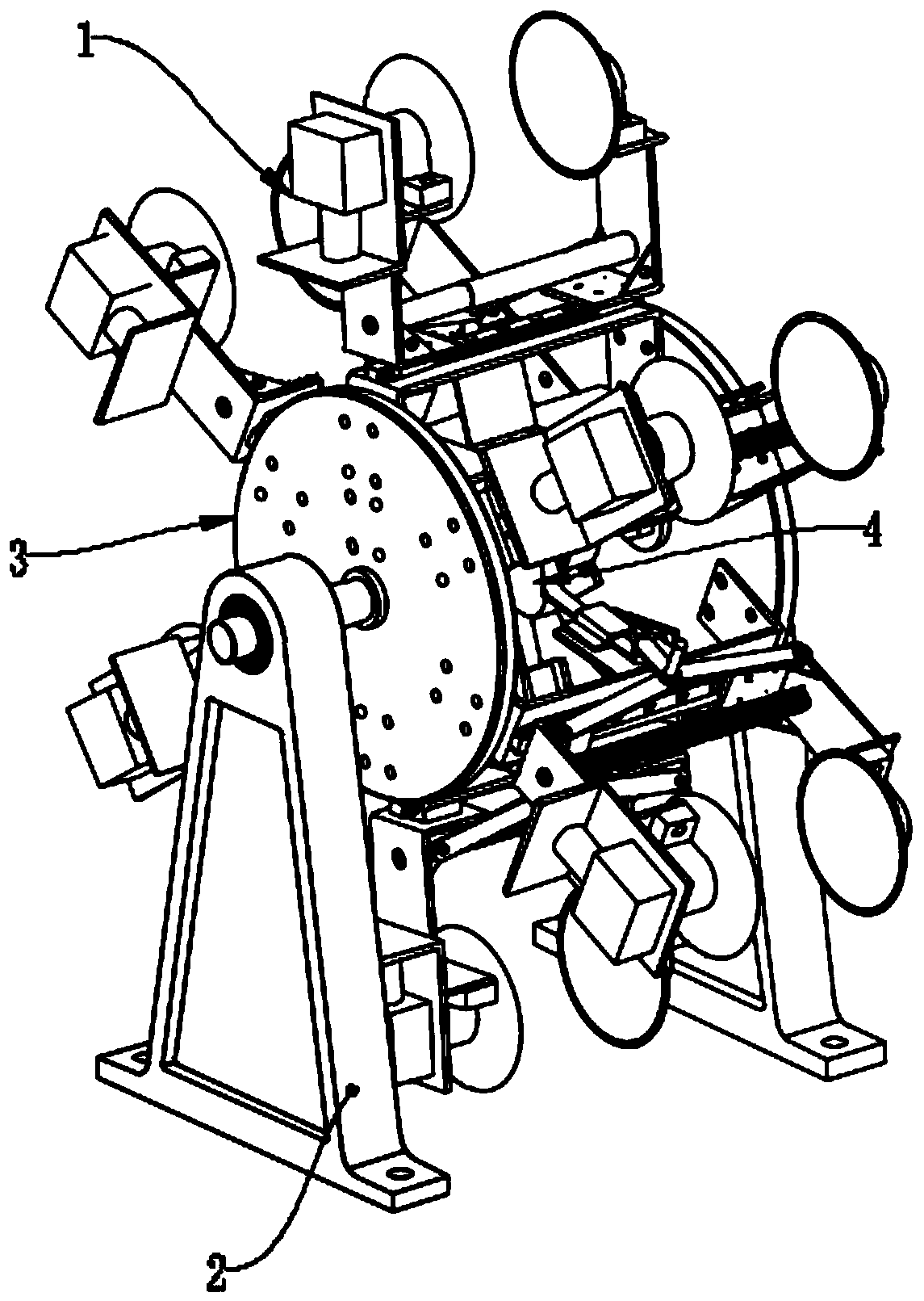
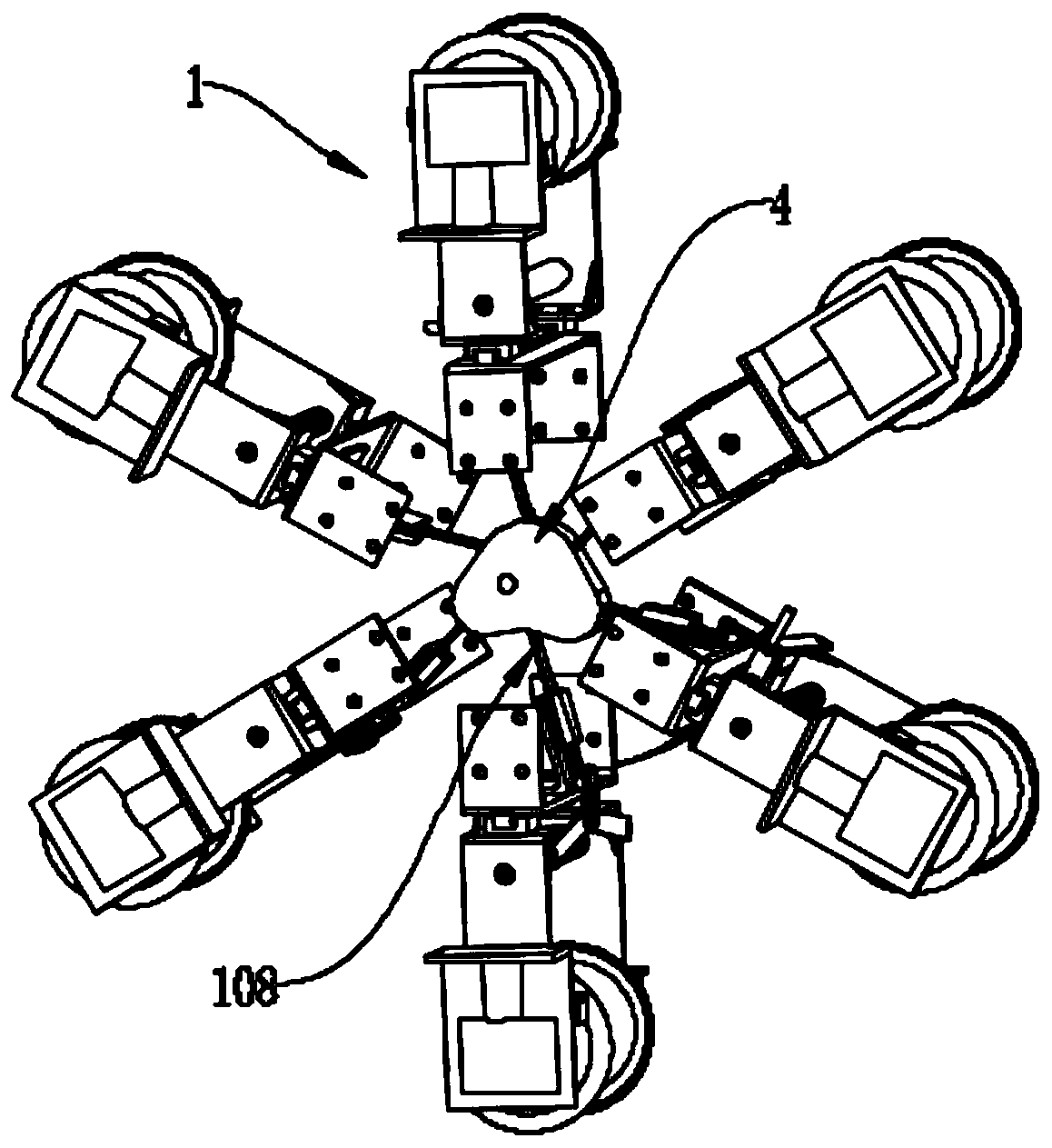
[0053] Such as Figure 1-Figure 5 An Apple posture fine adjustment device shown includes a frame, a rotating mechanism, a plurality of turning mechanisms 1 and a cam 4; the rotating mechanism can be rotatably mounted on the bracket, and the rotating mechanism is equipped with a driving mechanism for driving its rotation ; A plurality of turning mechanisms 1 are uniformly installed on the outer circumference of the turning mechanism in an annular and equidistant manner, used to pick up the placed apples, and transfer the apple turning fruits to the upper box mechanism with the stalk upward; the cam 4 is installed on the frame It is located on the inner side of the rotating mechanism and is configured to drive the turning mechanism to clamp the apple.
[0054] Specifically, the frame is two sets of oppositely arranged support frames 2, and the rotation mechanism is two oppositely arranged turntables 3, and the two turntables 3 are respectively installed and rotatably mounted on the two sets of support frames 2.
[0055] It is worth noting that the cam 4 has two protruding parts 401 and 402, which are used to drive the turning mechanism to pick up and put down the apple, respectively. The cam 4 is fixed to the right support frame 2 by a fixed shaft 5. The fixed shaft 5 is fixed on the right side of the right support frame 2. The turntable 3 on the right is rotatably mounted on the fixed shaft 5, and the cam 4 is fixed on the fixed shaft. 5 is located in the middle between the two turntables 3, the turntable 3 on the left is rotatably connected to the support frame 2 on the left through the shaft 6, and the two turntables 3 on the left and right are connected to each other through the sliding seat of the turning mechanism, practical application At this time, the rotating shaft 6 is driven to rotate by the driving device, thereby driving the two turntables 3 and the turning mechanism 1 to rotate. The fixed shaft 5 is a fixed link with the right side support frame 2 and the cam 4, and the cam 4 is always arranged directly on the two turntables 3 at a fixed position. In other embodiments, in order to make the fixed shaft 5 more stable and fix the position of the cam 4, a shaft seat 7 through which the fixed shaft 5 can pass is installed on the inner side of the two turntables. 7 are located at the two ends of the cam respectively. The fixed shaft and the shaft hole of the shaft base 7 are fitted with bearings to realize the radial positioning of the fixed shaft 5. Since the shaft base 7 is fixed on the turntable 3 and rotatably cooperates with the fixed shaft 5, When the turntable 3 rotates, the shaft base 7 can be rotated together.
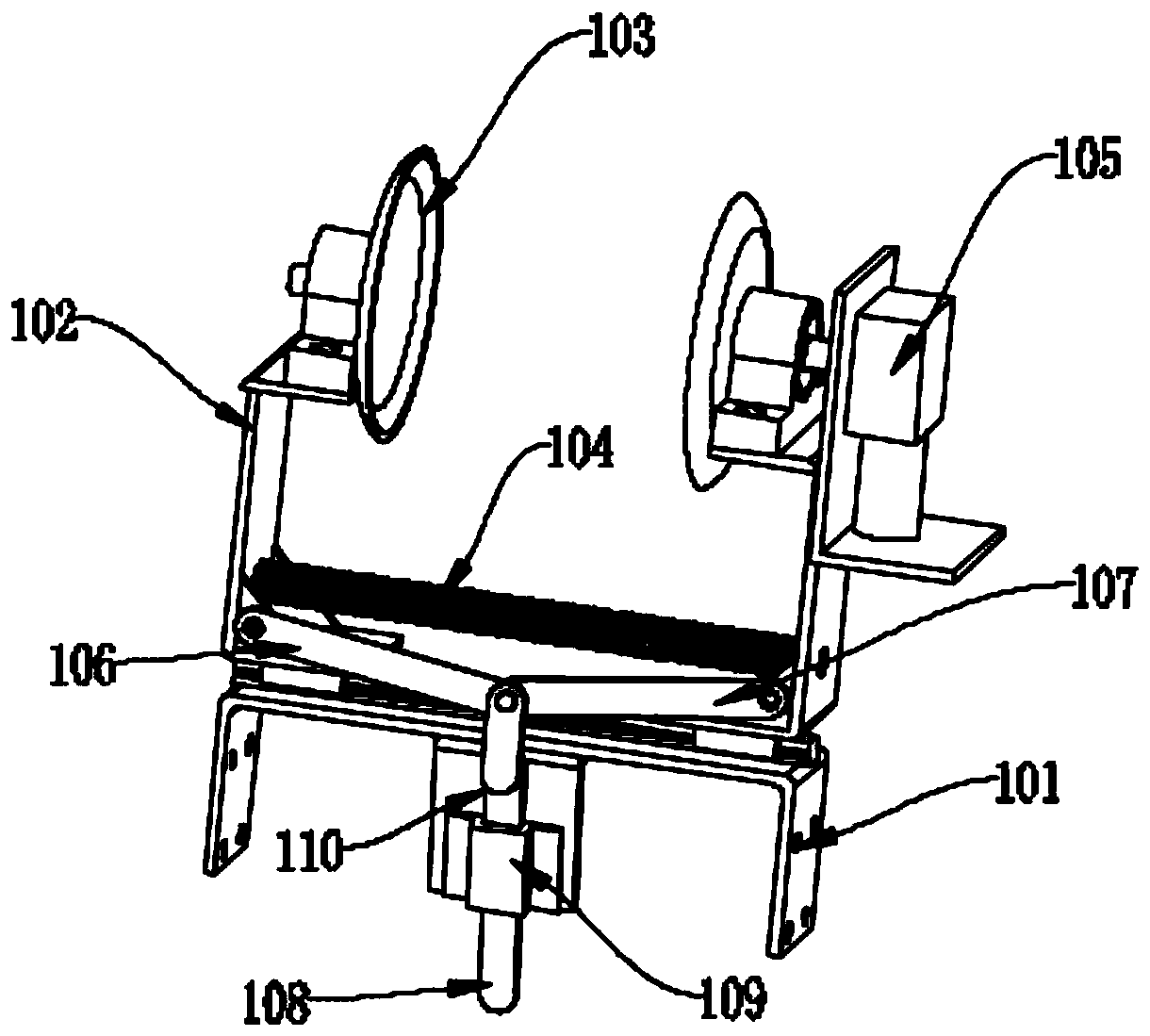
[0056] In this embodiment, refer to figure 2 , The turning mechanism 1 includes a sliding seat 101, two sets of sliding frames 102, two clamping turntables 103, a tension spring 104, a three-link mechanism, and a turning motor 105; wherein, the three-link mechanism includes three ends through shaft pins Pivotally connected rod one 106, rod two 107, and rod three 108; the two ends of the sliding seat 101 are respectively fixed to the two turntables 3; the two sets of sliding frames 102 are slidably mounted on the sliding seat 101 and face the turntable 3 on the outer ring side; two clamping turntables 103 can be mounted on the two sets of carriages 102 respectively, and are arranged oppositely; the turning motor 105 is mounted on one of the carriages 102 and clamped with the carriage 102 The turntable 103 is drivingly connected; the two ends of the tension spring 104 are respectively connected to the two sets of carriages 102 for clamping the two sets of carriages 10; the other ends of the rod one 106 and the rod two 107 are hinged to the two sets of carriage 102, respectively. The other end of the three 108 extends to the cam. When the three rod 108 rotates to the protruding parts 401 and 402 of the cam, the three rod 108 faces away from the cam side, and then the two clamps are opened by the rod one 106 and the rod two 107 The turntable 103, when the rod three 108 leaves the protruding parts 401, 402 of the cam, under the action of the tension spring 104, the two clamping turntables 103 move closer to each other; the two clamping turntables 103 are expanded and clamped to achieve For clamping an apple, when the clamping turntable 103 clamps the apple, the turning motor 105 drives the clamping turntable 103 to rotate to realize turning over the apple, so as to adjust the posture of the apple.
[0057] Further, there is a sliding cavity seat 109 on the side of the sliding seat 101 through which the rod three 108 can pass, and the side surface of the connecting end of the rod three 108 and the other two rod bodies has a step that can limit the sliding cavity seat 109. 110. Under the limiting action of the sliding cavity seat 109 and the step 110, the rod three 108 can withstand the rod one 106 and the rod two 107 at the limit position, thereby controlling the distance between the two clamping turntables 103 to move together.
[0058] More specifically, the sliding seat 101 is provided with a sliding rail, and the sliding frame 102 has a sliding part that cooperates with the sliding rail. The sliding frame 102 is movably installed on the sliding seat 101 through the sliding rail and the sliding block; the top of the sliding frame 102 is equipped with a shaft The clamping turntable 103 is rotatably installed through a rotating shaft and a shaft base on one side thereof, and the turning motor 105 is drivingly connected with the rotating shaft to drive the clamping turntable 103 to rotate.
[0059] When the present invention is in practical application, an infrared pair of tube detection device is set at the feeding position of the apple to detect that the fruit stalk end of the apple is facing up or down, and the infrared pair of tube detection device and the turning motor 105 of each turning mechanism 1 are both Controlled by programmable controller. Specifically, the left side of the rotating mechanism that rotates clockwise is the clamping side, and the right is the discharging side. The protruding parts 401 and 402 of the cam are located on the clamping side and the discharging side respectively. When the turning mechanism 1 is rotated to approach the clamping side When the side is turned, the end of the rod three 108 is turned to the protruding part 401 and the rod three 108 is pushed out by it to open the two sets of sliding frames 102 so that the distance between the two clamping turntables 103 can accommodate the apple. 1 When the apple is about to be connected to the external device, the end of the rod 108 leaves the protruding part 401, and the two clamping turntables 103 are clamped, thereby clamping the apple and removing the apple. The turning mechanism drives the turning mechanism 1 to rotate until it is close to unloading. When the material side, the end of the rod three 108 is turned to the protruding part 402 and the rod three 108 is pushed out by it, and the two sets of sliding frames 102 are opened to open the two clamping turntables 103 to unload the apple at the unloading position. After the ends of the three 108 leave the protruding part 402, the two clamping turntables 103 return to their original positions. When the rotating mechanism drives the turning mechanism 1 to move to the discharge side, the turning motor 105 drives the clamping turntable 103 to rotate at the same time, so that the end of the unloaded apple fruit stem faces upward, and the turning motor 105 is controlled by the programmable controller. The clamping turntable 103 is turned at a specific angle. In this embodiment, the axis of the rotating mechanism is taken as the center, and the angle between the clamping position and the unloading position is n. When the infrared pair tube detection device detects the installation When the pedicle end of the apple fruit is facing upward during clamping, the turning motor 105 will drive the clamping turntable 103 to turn the rotating mechanism to reverse the direction of turning by n degrees. When the infrared pair tube detection device detects that the apple fruit top is upward when clamping At this time, the turning motor 105 drives the clamping turntable 103 to turn 180+n degrees in the reverse direction of the rotating mechanism, so as to accurately adjust the placement posture of the apple to facilitate the subsequent netting and boxing operations.
[0060] The driving mechanism in this embodiment is a motor arranged on one of the support frames 2, and the motor is drivingly connected to the turntable 3 on the support frame 2 to drive the rotation mechanism to rotate, thereby driving the multiple turning mechanisms 1 around the two turntables 3 The axis rotates.
[0061] In another aspect of the present invention, there is also provided an attitude adjustment device, see Figure 6-Figure 8 , Which includes the above-mentioned Apple attitude fine posture device, and adds a coarse adjustment device, which specifically includes a main frame 201, a feeding belt 202, a coarse adjustment device and a posture fine adjustment device 203: the feeding belt 202 is set on the main frame One end on 201; the coarse adjustment device is set on the main frame 201 and is located on the discharge side of the upper material belt 202, and is used to receive the apple output from the upper material belt 202 and adjust it to be placed with the top of the fruit or the end of the fruit stalk facing upwards The posture fine adjustment device 203 is arranged on the main frame 201 and is located on the other side of the coarse adjustment device; before the apple netting operation, the posture of the apple is precisely adjusted through it, and the apple feeding belt 202 is loaded It is conveyed to the coarse adjustment device, and the apple's posture is roughly adjusted on the coarse adjustment device, so that the pedicle end or the top of the apple is placed up and sent to the posture fine adjustment device 203. After the posture fine adjustment device 203 adjusts, The fruit stalks of all apples face upward.
[0062] In this embodiment, the coarse adjustment device includes an inclined conveyor belt 204, a horizontal conveyor belt 205, and a brush 206; the inclined conveyor belt 204 is installed on the main frame 201 obliquely along the side of the fine posture adjustment device 203; The belt 205 is arranged between the inclined conveyor belt 204 and the posture fine adjustment device 203; the brush 206 is arranged above the inclined conveyor belt 204 through the mounting frame 208 fixed on the main frame 201. When the apple posture is roughly adjusted, the apple is The feeding belt 202 is sent to the inclined conveyor belt 204, and the inclined conveyor belt 204 is inclined upward for transmission. Because the circumference of the apple is similar to a circular structure, in the inclined state, when the stalk end or the top of the fruit contacts the inclined surface, the apple will not Rolling occurs. When the side of the apple, that is, the pulp part, is in contact with the inclined surface, the apple will roll until the pedicle end or the top of the fruit touches the inclined surface, and a brush 206 is set above the inclined conveyor belt 204, Make the apples better turn to the state where the stalk end or the top of the fruit is in contact with the inclined surface. In this state, the apples are transported to the top of the inclined conveyor belt 204 until they are transported to the horizontal conveyor belt 205, thereby completing the rough adjustment of the apple posture and by The horizontal conveyor belt 205 is sent to the fine posture adjustment device 203 for fine posture adjustment of the apple.
[0063] More specifically, the inclined conveyor belt 204 forms an inclined structure by the height of the mounting seat on one side being higher than the height of the other side. The rack is installed with baffles 209 on both sides of the inclined conveyor belt 204. A limit wheel 210 is set in the middle of the inner side. The upper belt surface of the conveyor belt can be pressed down by the limit wheel to form a horizontal section 211 and an inclined section 212. The horizontal section 211 is close to the side of the feeding belt 202. 211 in order to achieve better feeding and prevent the apple from rolling back to the feeding belt 202 when it rolls off.
[0064] It is worth noting that the belt surface width of the horizontal conveyor belt 205 is smaller than the diameter of the apple, and its end close to the end of the fine posture adjustment device 203 is located in the clamping space of the two clamping turntables 103 of the fine posture adjustment device 203.
[0065] It should also be noted that there are two discharging baffles 215 on both sides of the inclined conveyor belt 204 and the horizontal conveying belt 205. Between the two discharging baffles 215 is the apple output channel 213, and the horizontal conveyor belt 204 The mouth of the output channel 213 at one end is smaller than the mouth at the other end, which allows only one apple to pass through, so that the apples are transported to the horizontal conveyor belt 205 in a single row.
[0066] In this embodiment, the feeding belt 202 adopts a wave-shaped conveyor belt, so as to better convey the apples to the coarse adjustment device.
[0067] In this embodiment, the main frame 201 is also provided with an infrared pair tube detection device 214 for detecting the pedicle end of the apple or the top end of the fruit facing upwards, to cooperate with the posture fine adjustment device 203 to perform fine adjustment of the posture of the apple. The detection device 214 is located on the side of the horizontal conveyor belt 205 close to the end of the posture fine adjustment device 203; in actual application, the infrared pair tube detection device 214 and each turning motor 105 are controlled by connecting a programmable controller, due to the projection of the fruit stalk end of the apple The area is larger than the projected area of the top of the fruit, and then the tube detection device 214 is detected and recognized by infrared, and the posture fine adjustment device 203 is used for precise adjustment.
[0068] In this embodiment, a discharge conveyor belt 207 is provided on the other side of the posture fine adjustment device 203. The width of the discharge conveyor belt 207 is smaller than the diameter of the apple, and its end close to the end of the posture fine adjustment device 203 is in the posture. In the clamping space of the two clamping turntables 103 of the fine adjustment device 203, the adjusted posture apples are output through the discharge conveyor 207.
[0069] In order to better improve efficiency, both the coarse adjustment device and the posture fine adjustment device 203 are provided with at least two groups, and they are both arranged in the above-mentioned structure; on the basis of the two groups, in order to simplify the driving structure, the inclination of the coarse adjustment device The drive shafts of the conveyor belt 204 and the horizontal conveyor belt 205 adopt a coupling structure design, and the rotating shaft 6 of the posture fine adjustment device 203 also adopts a coupling design, so the two sets of devices can be driven by the same driving source.
[0070] In some embodiments, a hopper 215 is provided at the feeding end of the feeding belt 202 on the main frame 201.
[0071] In some embodiments, an upper boxing mechanism 300 may be provided at the end of the main frame 201 near the discharge conveyor belt 207, so that the adjusted posture of the apples can be quickly boxed. The upper boxing mechanism 300 includes a frame body, a netting device and a boxing device arranged on the frame, and a netting manipulator and a boxing manipulator arranged above the frame. The netting manipulator grasps the apples on the discharge conveyor belt. Take the netting device for netting, the boxing manipulator grabs the netted apples into the box on the boxing device, and integrates the boxing mechanism to form a complete apple packaging process.
[0072] The above are only the preferred embodiments of the present invention, and do not limit the scope of the present invention. Under the inventive concept of the present invention, equivalent structural transformations made by using the contents of the description and drawings of the present invention, or direct/indirect use Other related technical fields are included in the scope of patent protection of the present invention.