Film laminating machine and film laminating method for curved surface parts of flywheel car shell

A flywheel car and film laminating machine technology, applied in packaging and other directions, can solve problems such as low film laminating efficiency on curved surfaces, affecting assembly operations, and shell corrosion, achieving the effects of reducing film laminating costs, improving film lamination efficiency, and avoiding shedding

Active Publication Date: 2018-11-02
YIHE PRECISION IND SUZHOU
View PDF6 Cites 0 Cited by
  • Summary
  • Abstract
  • Description
  • Claims
  • Application Information

AI Technical Summary

Problems solved by technology

At present, most of the curved surface parts of the flywheel shell are laminated manually. Compared with the traditional flat film, the curved surface film has its own particularity when the artificial surface film is applied. Timely and skilled operators will inevitably produce film. Air bubbles will affect the sales of the product, and the surface of the shell surface parts will be frequently picked up when the film is applied manually. Sweat stains, fingerprints and dust will remain on the surface of the flywheel shell parts during the filming process, and the residual sweat stains will speed up the shell Corrosion of the body, fingerprints and dust will affect the subsequent assembly operations, and the surface of the housing components is easily scratched by sharp tools during the transportation and assembly process and during the pick-up process
In this way, the efficiency of surface film sticking is greatly reduced, and the man-hours required for film sticking increase, which greatly increases the production cost of the enterprise, and also increases the cost of post-processing.

Method used


Image

  • Film laminating machine and film laminating method for curved surface parts of flywheel car shell
  • Film laminating machine and film laminating method for curved surface parts of flywheel car shell
  • Film laminating machine and film laminating method for curved surface parts of flywheel car shell

Examples


Embodiment Construction

[0031] Below in conjunction with specific embodiment, content of the present invention is described in further detail:

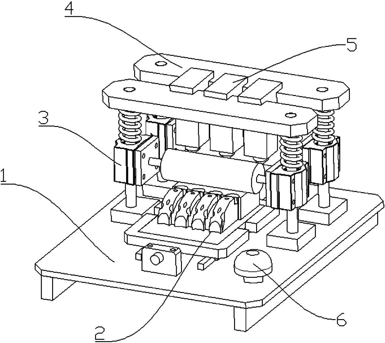
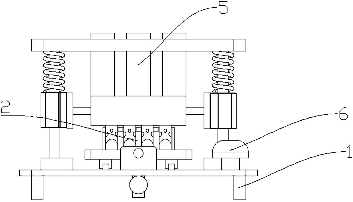
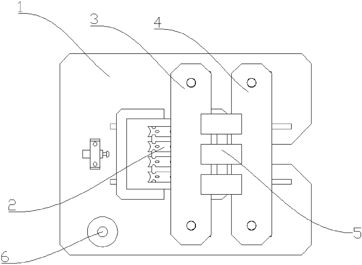
[0032] In order to achieve the purpose of the present invention, as shown in the figure, one embodiment of the present invention is: a film laminating machine for the curved surface parts of the flywheel car shell, including a base 1, a moving jig seat 2, a moving jig seat 2 and The base 1 is connected, including a moving mechanism and a jig base 16, the jig base 16 is connected to the moving mechanism, the jig base 16 is used to place curved surface components, and the moving mechanism is used to push the jig base 16 to move; dust removal device 3, dust removal device 3 It is connected with the base 1 and located above the mobile jig seat 2, and is used for dedusting the curved surface parts; the film sticking device 4, the film sticking device 4 is connected with the base 1, located above the mobile jig seat 2 and behind the dust removal device 3, It is us...


PUM


Abstract

The invention discloses a film sticking machine for curved parts of a gyrobus shell body. The film sticking machine for the curved parts of the gyrobus shell body comprises a base, a movable jig base, a dust removing device, a film sticking device and preheating devices. The movable jig base comprises a movable mechanism used for pushing a jig base to move and the jig base used for placing the curved parts; the dust removing device is used for dust removing on the curved parts; the film sticking device is used for film sticking on the curved parts; the preheating devices are used for preheating the curved parts. The film sticking machine has the advantages that the dust removing device, the preheating devices and the film sticking device are arranged; dust on the curved parts are removed, and then the dust removed curved parts are preheated, and finally films are stuck on the preheated curved parts; the stuck films can be firmer and not easy to fall off after cold shrinkage by preheating, so that the film sticking efficiency and the film sticking quality can be greatly improved, the film sticking cost of an enterprise can be greatly lowered and the phenomenon of stuck films falling off can be avoid.

Description

technical field [0001] The invention relates to the field of film laminating machines, in particular to a film laminating machine for curved surface parts of a flywheel car shell and a film laminating method thereof. Background technique [0002] At present, when assembling the curved surface parts of the flywheel car shell, it is necessary to stick a film on its surface for subsequent transportation and assembly operations. At present, most of the curved surface parts of the flywheel shell are laminated manually. Compared with the traditional flat film, the curved surface film has its own particularity when the artificial surface film is applied. Timely and skilled operators will inevitably produce film. Air bubbles will affect the sales of the product, and the surface of the shell surface parts will be frequently picked up when the film is applied manually. Sweat stains, fingerprints and dust will remain on the surface of the flywheel shell parts during the filming process...

Claims


Application Information

Patent Timeline
Patent Type & Authority Patents(China)
IPC IPC(8): B65B33/02
CPCB65B33/02
Inventor 谈多多
Owner YIHE PRECISION IND SUZHOU
Why Eureka
Try Eureka