
A locking structure for rotor blades

A technology of rotor blade and locking structure, which is applied in the direction of supporting elements of blades, machines/engines, mechanical equipment, etc., to achieve the effect of reliable positioning

Active Publication Date: 2019-03-08
AECC SHENYANG ENGINE RES INST
View PDF4 Cites 2 Cited by
  • Summary
  • Abstract
  • Description
  • Claims
  • Application Information

AI Technical Summary

Problems solved by technology

[0004] The purpose of the present invention is to provide a rotor blade locking structure to solve or at least alleviate at least one of the problems in the background art

Method used


Image

  • A locking structure for rotor blades
  • A locking structure for rotor blades
  • A locking structure for rotor blades

Examples


Embodiment Construction

[0023] In order to make the objectives, technical solutions and advantages of the present invention clearer, the technical solutions in the embodiments of the present invention will be described in more detail below in conjunction with the drawings in the embodiments of the present invention. In the drawings, the same or similar reference numerals denote the same or similar elements or elements having the same or similar functions throughout. The described embodiments are some, but not all, embodiments of the invention. The embodiments described below by referring to the figures are exemplary and are intended to explain the present invention and should not be construed as limiting the present invention. Based on the embodiments of the present invention, all other embodiments obtained by persons of ordinary skill in the art without creative efforts fall within the protection scope of the present invention. Embodiments of the present invention will be described in detail below ...


PUM


Abstract

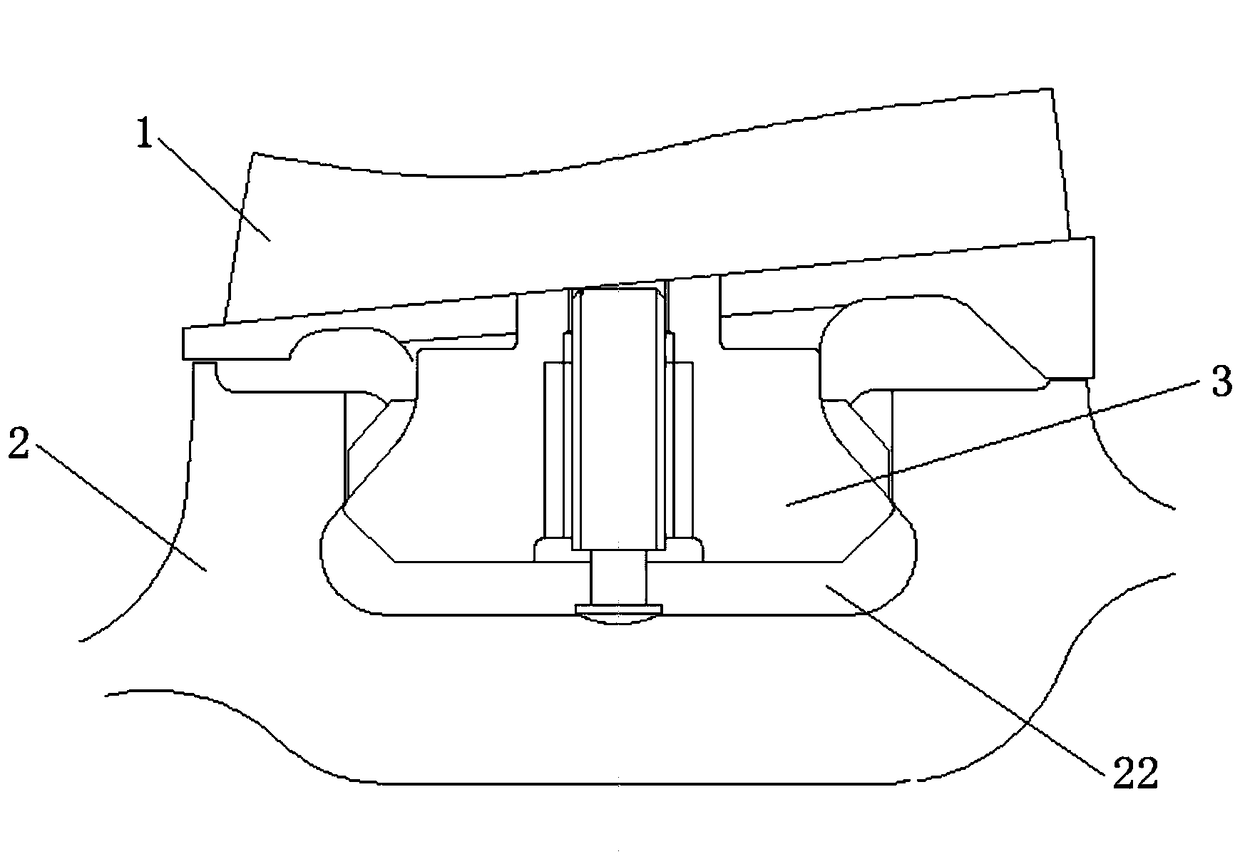
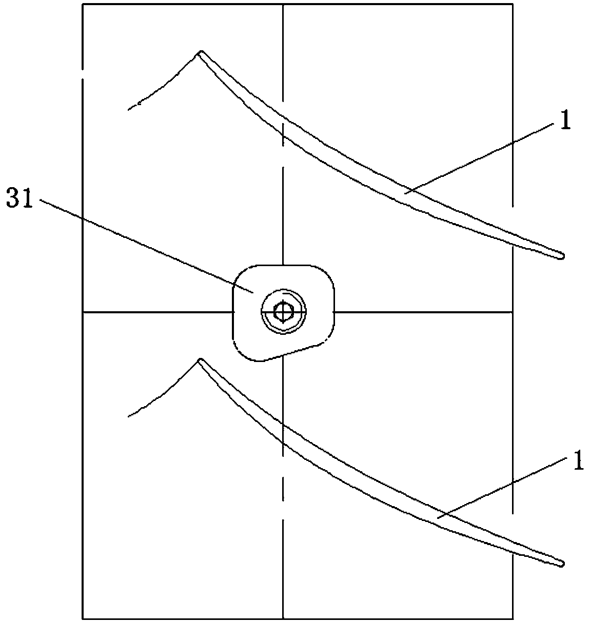
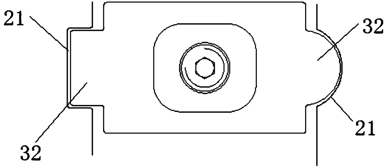
The invention discloses a rotor vane locking structure, and relates to the technical field of engines. The rotor vane locking structure comprises rotor vanes, a drum and a locking block, wherein the rotor vanes are mounted in mortises in the drum through tenons, and are locked in the circumferential direction of the drum through the locking block; a first profile is arranged at one end of the locking block; a second profile is arranged at the other end, opposite to the first profile, of the locking block; half-profile grooves are formed in margin plates of the rotor vanes; the half-profile grooves at the two adjacent rotor vanes form an integral groove fit with the first profile; a clamping groove fit with the second profile is formed in the drum; and at least one of the first profile and the second profile is dissymmetric. The rotor vane locking structure has the benefits that the rotor vane locking structure can prevent the locking block from being mounted reversely at the axial front and back of the drum through the first profile or the second profile.

Description

technical field [0001] The invention relates to the technical field of engines, in particular to a locking structure for rotor blades. Background technique [0002] The function of the locking block is mainly used for the circumferential locking of the circumferential dovetail tenon rotor blades. The locking block is positioned between the tenon-groove mating surface of the drum and the card groove, and is located between the two rotor blades in the circumferential direction. The rotor blade edge plate corresponding to the upper end of the block is slotted, and the upper end of the locking block cooperates with the edge plate groove to realize the circumferential locking of the rotor blade. [0003] The mating surface of the locking block and the drum is a symmetrical structure. During the assembly process, the axial direction of the locking block is easily reversed, causing the upper end of the locking block to protrude from the flow path and affect the performance. Conte...

Claims


Application Information

Patent Timeline
Patent Type & Authority Patents(China)
IPC IPC(8): F01D5/32
CPCF01D5/326
Inventor 于连超印雪梅赵雷白志刚高兴韩方军李惠莲翟贤超
Owner AECC SHENYANG ENGINE RES INST
Learn More