
Open accessory with spring tension

A technology of mounting parts and spring parts, applied in the direction of pipe components, pipes/pipe joints/fittings, pipe supports, etc., which can solve the problems of scattered errors of line compression rings, inability to guarantee functions (damping or isolation, difficult installation, etc.)

Inactive Publication Date: 2016-10-12
WITZENMANN METAL PROD JIANGYIN CO LTD
View PDF6 Cites 2 Cited by
  • Summary
  • Abstract
  • Description
  • Claims
  • Application Information

AI Technical Summary

Problems solved by technology

This is considered disadvantageous in some cases, for example, when the components are brazed in the furnace or when there are possible connections that do not allow the subsequent installation of the wire clamping ring, which is not necessary from the point of view of processing technology. Less than
[0003] Furthermore, it has proven to be disadvantageous that in the previously used wire clamping rings, the radial force required for fastening to the pipeline can be very variable depending on the tolerances of the pipe parts or the wire clamping rings
This can lead to the failure of the desired function (damping or isolation), or even the slipping of the wire compression ring from the pipe or the corrugation pleats
It is also known that the opposite is the case: the wire clamping ring may adhere tightly due to tolerances, with the result that it can only be installed with difficulty

Method used


Image

  • Open accessory with spring tension
  • Open accessory with spring tension
  • Open accessory with spring tension

Examples


Embodiment Construction

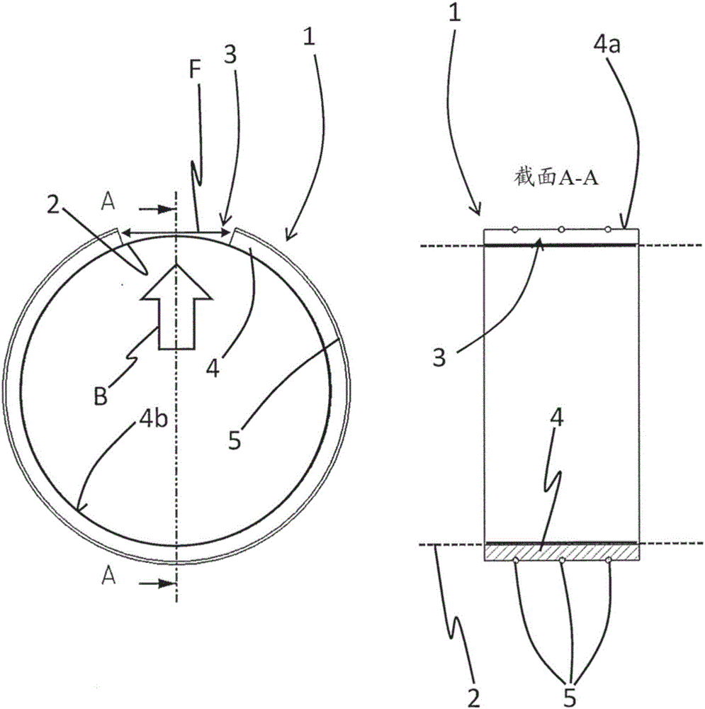
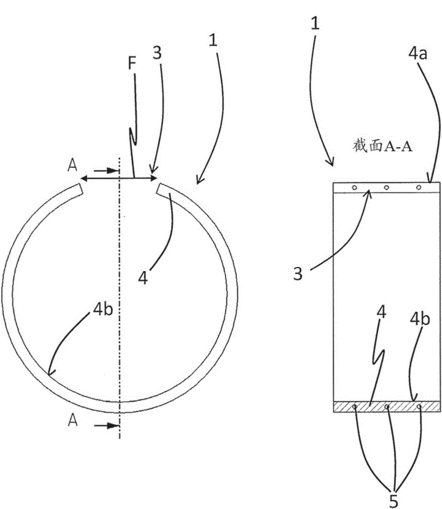
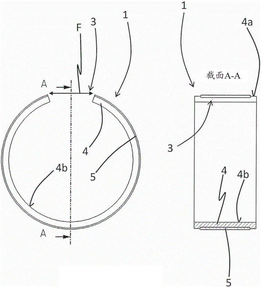
[0048] in figure 1 The mounting member 1 of the present invention is shown in the state where it is installed on the pipeline 2. In the view part on the left, the front view shows the arrangement structure; in the right part, the arrangement structure is shown in a longitudinal sectional view along the line A-A in the view part on the left. The pipe 2 has a circular cross section in the illustrated embodiment and can be constructed in the form of a corrugated pipe or a hose or in the form of a corrugated sleeve. figure 1 Is not explicitly shown in. In addition, it is considered that the pipeline 2 only has a crooked portion locally.

[0049] The mounting part 1 is formed in the form of a ring, which has a notch at the reference number 3. The mounting member 1 includes a main body denoted by the reference numeral 4, and on its outer surface 4a, the main body has three spring members in the form of annular springs arranged in parallel and equidistant from each other. figure 1 It i...


PUM


Abstract

The invention relates to an open accessory with spring tension and provides an add-on part (1) for a line element (2), comprising: a substantially annular basic body (4) which has an interruption (3) in at least one region of its circumference; And at least one substantially annular spring element which has an opening in at least one region of its circumference, wherein the spring element is arranged or arrangeable such that it allows expansion of the base body in the region of the interruption, 3). The invention also relates to a method for damping or isolating a line (2), in particular a line (2) with at least one corrugated section, by means of at least one such component (1) and a correspondingly equipped line (2).

Description

Technical field [0001] The present invention relates to a mounting piece for a pipeline component according to claim 1, a pipeline according to claim 14, and a pipeline damping or isolation method according to claim 17 or 18. Background technique [0002] In order to dampen and / or isolate pipelines or pipelines that are at least partially corrugated or formed in a corrugated sleeve shape, it is especially known from the prior art to use a wire compression ring, which is often sleeved in the form of a closed ring. Piping or corrugated folds. At this time, it is considered disadvantageous in some cases, such as when these components are brazed in the furnace or when there may be connections that do not allow the line compression ring to be installed afterwards. This is done from the perspective of processing technology. Less than. [0003] In addition, it has proved to be disadvantageous that in the wire compression ring used so far, the radial force required for fixing on the pipe...

Claims


Application Information

Patent Timeline
IPC IPC(8): F16L55/04
CPCF16L55/0335F16L3/06F16L55/0336F16L59/21F16L55/04
Inventor 埃尔克·幕赫鲍尔迈克尔·普拉斯柴克马吕斯·瑞特兹
Owner WITZENMANN METAL PROD JIANGYIN CO LTD
Learn More