
Ash fusibility tester and image taking method thereof

A kind of technology of ash fusion tester, which is applied in the field of ash fusion tester and its imaging, can solve the problems of low test efficiency of ash fusion tester and complex design of furnace tube, so as to improve sample test efficiency and energy The effect of utilization

Inactive Publication Date: 2016-10-12
长沙开元仪器有限公司
View PDF8 Cites 0 Cited by
  • Summary
  • Abstract
  • Description
  • Claims
  • Application Information

AI Technical Summary

Problems solved by technology

[0005] The technical problem to be solved by the present invention is to solve the problem of low test efficiency of the ash fusion tester and complex furnace tube design

Method used


Image

  • Ash fusibility tester and image taking method thereof
  • Ash fusibility tester and image taking method thereof
  • Ash fusibility tester and image taking method thereof

Examples


Embodiment 1

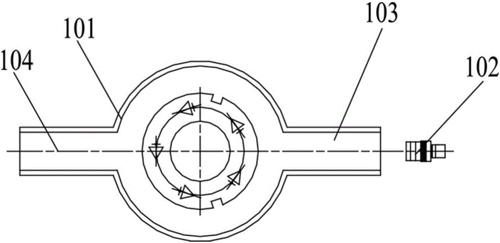
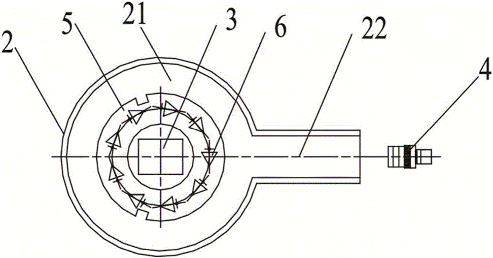
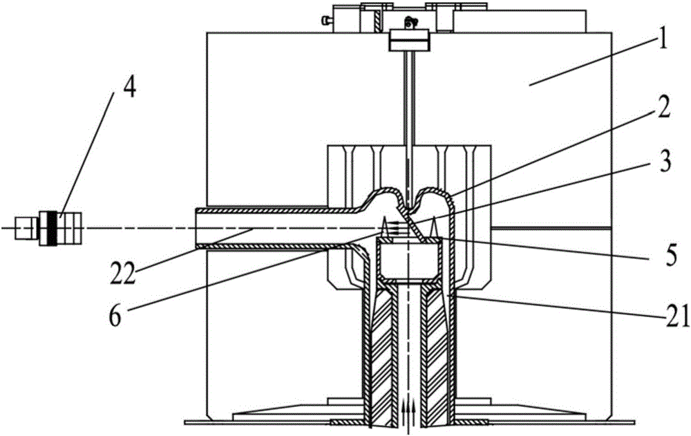
[0031] Such as figure 2 and image 3 As shown, an ash fusion tester provided by an embodiment of the present invention includes a high-temperature furnace 1, a furnace tube 2, a background plate 3, an imaging assembly 4 and a disc-shaped ash cone support plate 5 The furnace tube 2 is set in the high temperature furnace 1, the ash cone supporting plate 5 is set in the furnace tube 2, and the bottom of the ash cone supporting plate 5 is provided with a rotating mechanism for driving the ash cone supporting plate 5 to rotate in the furnace tube 2. The image taking assembly 4 is used to obtain the image of the ash cone 6 on the ash cone support plate 5 . Specifically, the furnace tube 2 includes an ash cone cavity 21 and an imaging cavity 22 arranged vertically to the ash cone cavity 21 . The ash cone supporting plate 5 is arranged in the ash cone cavity 21, and the image of the ash cone 6 in the ash cone cavity 21 reaches the image pickup assembly 4 through the imaging cavity ...

Embodiment 3

[0040] This embodiment provides a method for taking images of the ash fusion tester of Embodiment 1, comprising the following steps:

[0041] S1, the light in the low temperature area is incident on the background plate 3 to form a dark reflective surface;

[0042] S2, driving the ash cone supporting plate 5 to rotate;

[0043] S3 , the imaging assembly 4 photographs the ash cone 7 located between the background plate 3 and the imaging assembly 4 .

Embodiment 4

[0045] The present embodiment provides a kind of imaging method of the ash fusion tester of embodiment 2, comprises the following steps:

[0046] S1, the light in the low temperature area is incident on the background plate 3 to form a dark reflective surface;

[0047] S2, driving the ash cone supporting plate 5 to rotate;

[0048] S3, the imaging assembly 4 photographs the ash cone 7 located between the background plate 3 and the low temperature area according to the light reflected by the background plate 3 .


PUM


Abstract

The invention relates to the technical field of coal quality detection and analysis, and in particular relates to an ash fusibility tester and an image taking method thereof. The ash fusibility tester comprises a high temperature furnace, a furnace tube, a background plate, an image taking assembly and a disc-shaped ash cone supporting plate, wherein the furnace tube is arranged in the high temperature furnace, the ash cone supporting plate is arranged in the furnace tube, and a rotating mechanism for driving the ash cone supporting plate to rotate in the furnace tube is arranged below the ash cone supporting plate; the image taking assembly is used for acquiring an image of an ash cone on the ash cone supporting plate; the background plate is disposed in the middle part of the ash cone supporting plate, the upper edge of the background plate is connected with the top of the furnace tube, the lower edge of the background plate is disposed below the upper surface of the ash cone supporting plate, the background plate is a mirror-face reflection device, a reflection surface of the background plate faces a low temperature area of the furnace tube, and the image taking assembly faces a reflection end of the reflection surface of the background plate. By adopting the ash fusibility tester, the test efficiency is increased, and the furnace tube is simple in structure.

Description

technical field [0001] The invention relates to the technical field of coal quality detection and analysis, in particular to an ash fusion tester and an imaging method thereof. Background technique [0002] The ash melting test instrument is an instrument used to detect the melting of the ash cone of the coal sample. The melting of the ash cone is directly related to whether there is sintering in the boiler of the power plant and the severity of the sintering, and has a great impact on the safe use of boilers and cement shaft kilns. . In the current ash melting tester, the coal sample ash cone is arranged on the support plate, and the support plate is fixed on the support cup. During the test, the support cup drives the supporting plate to rotate, so that the coal sample ash cone rotates in the constant temperature zone of the high-temperature furnace tube and heats up evenly until the coal sample ash cone reaches a molten state. During this process, the camera mechanism t...

Claims


Application Information

Patent Timeline
Patent Type & Authority Applications(China)
IPC IPC(8): G01N31/12G01N21/84
CPCG01N21/84G01N31/12
Inventor 罗建文罗彬彬杨海涛蒋义廖炼斌
Owner 长沙开元仪器有限公司
Learn More